


Quick Research
Generate reliable direction feasibility study reports for your R&D in just a few steps.

Technical Q&A
Discover and master advanced knowledge NOW. Basics, ideas, possibilities, all at once.

Find Solutions
As an expert in R&D theories, this can generate solutions to your technical problems instantly.

Evaluate Feasibility
Analyze your overall solution with one click, know your potential R&D risks in advance.

Monitor Landscape
Get weekly tech updates, stay abreast of the latest tech innovations and key insights.
A three-phase dual active bridge DC converter control system and control method
A DC converter, dual active bridge technology, used in control/regulation systems, DC power input conversion to DC power output, instruments and other directions, can solve problems such as slow response, achieve improved accuracy, fast stability and precise adjustment, Physically meaningful effects
- Summary
- Abstract
- Description
- Claims
- Application Information
AI Technical Summary
Problems solved by technology
Method used
Image

Examples
Embodiment 1
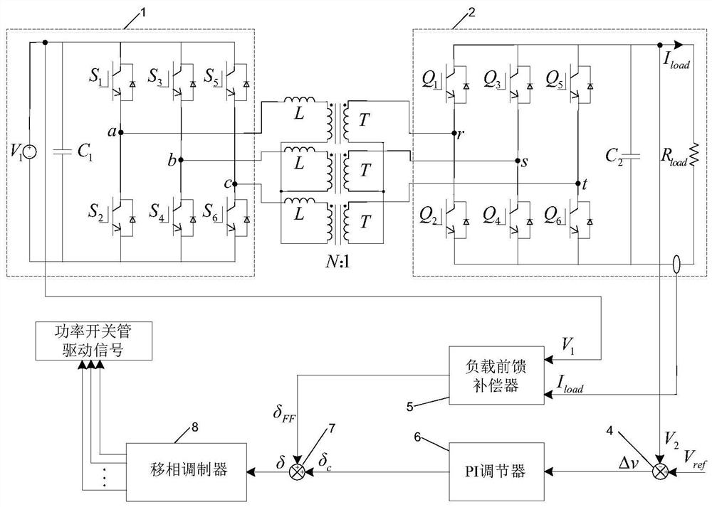
[0053] Such as figure 1 As shown, a three-phase dual active bridge DC converter control system includes a front-stage three-phase H-bridge inverter 1, a rear-stage three-phase H-bridge rectifier 2, three single-phase high-frequency transformers T, three A phase-shifting inductor L, the windings of the three single-phase high-frequency transformers T are connected to the front-stage three-phase H-bridge inverter 1 and the rear-stage three-phase H-bridge rectifier 2 according to a Y-Y-shaped connection mode, so that The three phase-shifting inductors L described above are respectively connected in series between the pre-stage three-phase H-bridge inverter 1 and the single-phase high-frequency transformer T; the three-phase dual active bridge DC converter control system also includes a power switch Tube drive system and load feed-forward compensation system.
[0054] The power switch tube drive system includes a first subtractor 4, a PI regulator 6, a first adder 7, a phase shif...
Embodiment 2
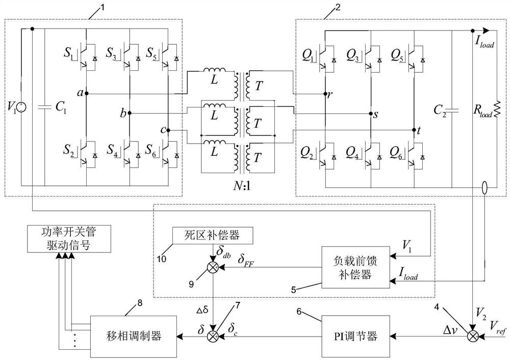
[0070] Such as figure 2 As shown, the difference between the three-phase dual active bridge DC converter control system of this embodiment and the first embodiment is that the load feed-forward compensation system also includes a second subtractor 9 and a dead zone compensator 10; The dead zone compensator 10 generates a phase shift angle command value δ for dead zone compensation db ; The second subtractor 9 will feed-forward compensation phase shift angle command value δ FF Phase shift angle command value δ with dead zone compensation db make difference to get δ FF -δ db , put δ FF -δ db Send into the first adder 7 and need to adjust the phase shift angle δ c Add to get the effective phase shift angle δ, that is, δ=δ c +δ FF -δ db .
[0071] The dead zone compensator 10 generates a phase shift angle command value δ for dead zone compensation db , is the command value of phase shift angle δ db The formula for calculating:
[0072]
[0073] Among them, δ s is...
Embodiment 3
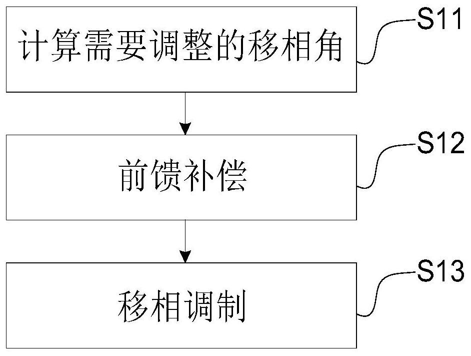
[0075] Such as image 3 As shown, a three-phase dual active bridge DC converter control method in this embodiment is applied to the control system described in Embodiment 1, and the control method includes the following steps: S11: Calculate the phase shift angle that needs to be adjusted ; S12: feedforward compensation, S13: phase shift modulation.
[0076] The control method of a three-phase dual active bridge DC converter in this embodiment has a clear physical meaning, is easy to analyze, and can well realize rapid stability and precise adjustment of the output voltage.
[0077] S11: Calculate the phase shift angle that needs to be adjusted, specifically:
[0078] The first subtractor 4 collects the system output DC voltage V 2 with a given output voltage reference V ref Make a difference to get the output voltage error signal Δv, and input the output voltage error signal Δv to the PI regulator to get the phase shift angle δ that needs to be adjusted c .
[0079] S12:...
PUM
 Abstract
Description
Claims
Application Information
 - R&D Engineer
- R&D Manager
- IP Professional
- Industry Leading Data Capabilities
- Powerful AI technology
- Patent DNA Extraction
Browse by: Latest US Patents, China's latest patents, Technical Efficacy Thesaurus, Application Domain, Technology Topic, Popular Technical Reports.
© 2024 PatSnap. All rights reserved.Legal|Privacy policy|Modern Slavery Act Transparency Statement|Sitemap|About US| Contact US: help@patsnap.com