
Oil well pump

A technology for oil well pumps and pump barrels, which is applied to pumps, pump components, variable displacement pump components, etc. It can solve the problems of increased oil well load, increased construction costs, and increased eccentric wear of sucker rods, so as to reduce downward resistance, Avoid leakage and ensure efficient operation

Inactive Publication Date: 2020-07-03
PETROCHINA CO LTD
View PDF4 Cites 0 Cited by
  • Summary
  • Abstract
  • Description
  • Claims
  • Application Information

AI Technical Summary

Problems solved by technology

However, in polymer injection pumping wells, the viscosity of the well fluid increases after meeting and mixing polymers, which increases the downward resistance of the sucker rod, and the alternating load increases, resulting in aggravated eccentric wear of the sucker rod.
[0003] At the same time, due to the increase of the viscosity of the well fluid, the sand-carrying ability of the well fluid is enhanced, and the resistance of the well fluid increases when the liquid flows through the gap between the plunger and the pump barrel, which leads to aggravated scaling and makes the gap between the plunger and the pump barrel It is easy to form friction between them, which will increase the load of the oil well, easily cause accidents such as eccentric wear, rod detachment, pump stuck, etc., and increase the difficulty of workover construction
However, it is necessary to replace the sucker rod of the whole well during the workover, which increases the construction cost

Method used


Image

  • Oil well pump
  • Oil well pump
  • Oil well pump

Examples


Embodiment Construction

[0034] In order to enable those skilled in the art to better understand the technical solutions in the present invention, the technical solutions in the embodiments of the present invention will be clearly and completely described below in conjunction with the drawings in the embodiments of the present invention. Obviously, the described The embodiments are only some of the embodiments of the present invention, not all of them. Based on the embodiments of the present invention, all other embodiments obtained by persons of ordinary skill in the art without making creative efforts shall fall within the protection scope of the present invention.

[0035] It should be noted that when an element is referred to as being “disposed on” another element, it may be directly on the other element or there may be another element in between. When an element is referred to as being "connected to" another element, it can be directly connected to the other element or it may be present interveni...


PUM


Abstract

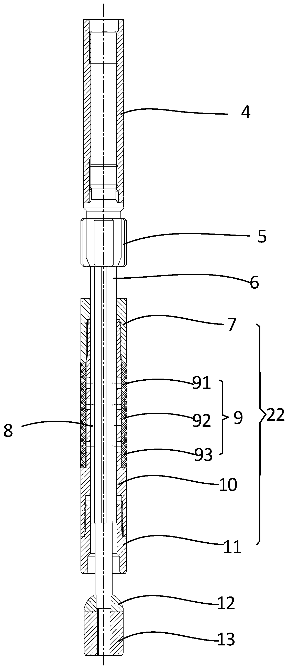
The invention discloses an oil well pump. The oil well pump includes a pump cylinder, a plunger assembly arranged in the pump cylinder, a central rod and a fixed valve assembly located below a travelling valve element, wherein the plunger assembly includes a plunger cylinder and an expansion sleeve sleeving outside the plunger cylinder, a radial through hole is formed in the cylinder wall of theplunger cylinder, the through hole is opposite to the expansion sleeve in the radial direction, a travelling valve seat is arranged at the lower end of the plunger cylinder, the plunger assembly sleeve the central rod, and a travelling valve element matched with the travelling valve seat is arranged at the lower end of the central rod; when the central rod drives the plunger assembly to move upwards, the travelling valve element is connected with the travelling valve seat, and the expansion sleeve is enlarged by the hydraulic pressure through the through hole to be fitted with the inner wall of the pump cylinder in a sealing mode; when the central rod drives the plunger assembly to move downwards, the travelling valve element is separated from the travelling valve seat, the expansion sleeve is reset to have an interval gap between the expansion sleeve and the pump cylinder.

Description

technical field [0001] The present application relates to the technical field of oil lifting, in particular to an oil well pump. Background technique [0002] As one of the important measures to enhance oil recovery, chemical composite flooding technology has been expanding its application scale year by year. However, in polymer injection pumping wells, the viscosity of the well fluid increases after meeting and mixing polymers, which increases the downward resistance of the sucker rod, and the alternating load increases, resulting in aggravated eccentric wear of the sucker rod. [0003] At the same time, due to the increase of the viscosity of the well fluid, the sand-carrying ability of the well fluid is enhanced, and the resistance of the well fluid increases when the liquid flows through the gap between the plunger and the pump barrel, which leads to aggravated scaling and makes the gap between the plunger and the pump barrel It is easy to form friction between them, wh...

Claims


Application Information

Patent Timeline
Patent Type & Authority Applications(China)
IPC IPC(8): F04B47/00F04B53/10F04B53/14F04B53/16
CPCF04B47/00F04B53/10F04B53/1002F04B53/1087F04B53/14F04B53/143F04B53/162F05C2225/00F05C2225/06F05C2225/12
Inventor 李立超王文钢张国龙于广刚杨志祥张曦宇梁兴卢玉吴钧高兰罗鹏飞吴建华江雪芹张红朋刘晓静王喜泉
Owner PETROCHINA CO LTD
Learn More