Self-heat-dissipation type power cabinet

A power cabinet and self-heating technology, which is applied to electrical components, substation/power distribution device shells, substation/switch layout details, etc., can solve problems such as poor ventilation, poor use of electrical appliances, etc.

Inactive Publication Date: 2020-06-30
胡从勇
View PDF4 Cites 11 Cited by
  • Summary
  • Abstract
  • Description
  • Claims
  • Application Information

AI Technical Summary

Problems solved by technology

[0003] The structure of various circuit components inside the power cabinet is relatively complex. When the electrical components in the power distribution cabinet are in high-load working conditions, a large amount of heat will be generated. If the heat is not dissipated in time, it will cause damage to the electrical components in the cabinet. damage, which can cause the electrical appliances supplied by the power cabinet to be unable to use normally, and cause electrical safety accidents in severe cases
[0004] The heat dissipation device of the existing power cabinet is generally provided with a heat dissipation groove on the side wall of the power cabinet, and then equipped with a heat dissipation fan for ventilation and heat dissipation, but in order to prevent sundries or water stains from entering the cabinet, the area of ​​the heat dissipation groove is generally small, which means As a result, the ventilation effect is not good, and the existing cooling fans generally require the operator to manually switch, which is not only time-consuming and troublesome, but also if the operator is slightly negligent and fails to turn on the cooling fan in time, it may cause the power cabinet to dissipate heat in time, thereby causing bad Consequences, and the motor part of the cooling fan will also generate a certain amount of heat when it is working, and the cooling effect is not ideal

Method used


Image

  • Self-heat-dissipation type power cabinet
  • Self-heat-dissipation type power cabinet
  • Self-heat-dissipation type power cabinet

Examples


Embodiment 1

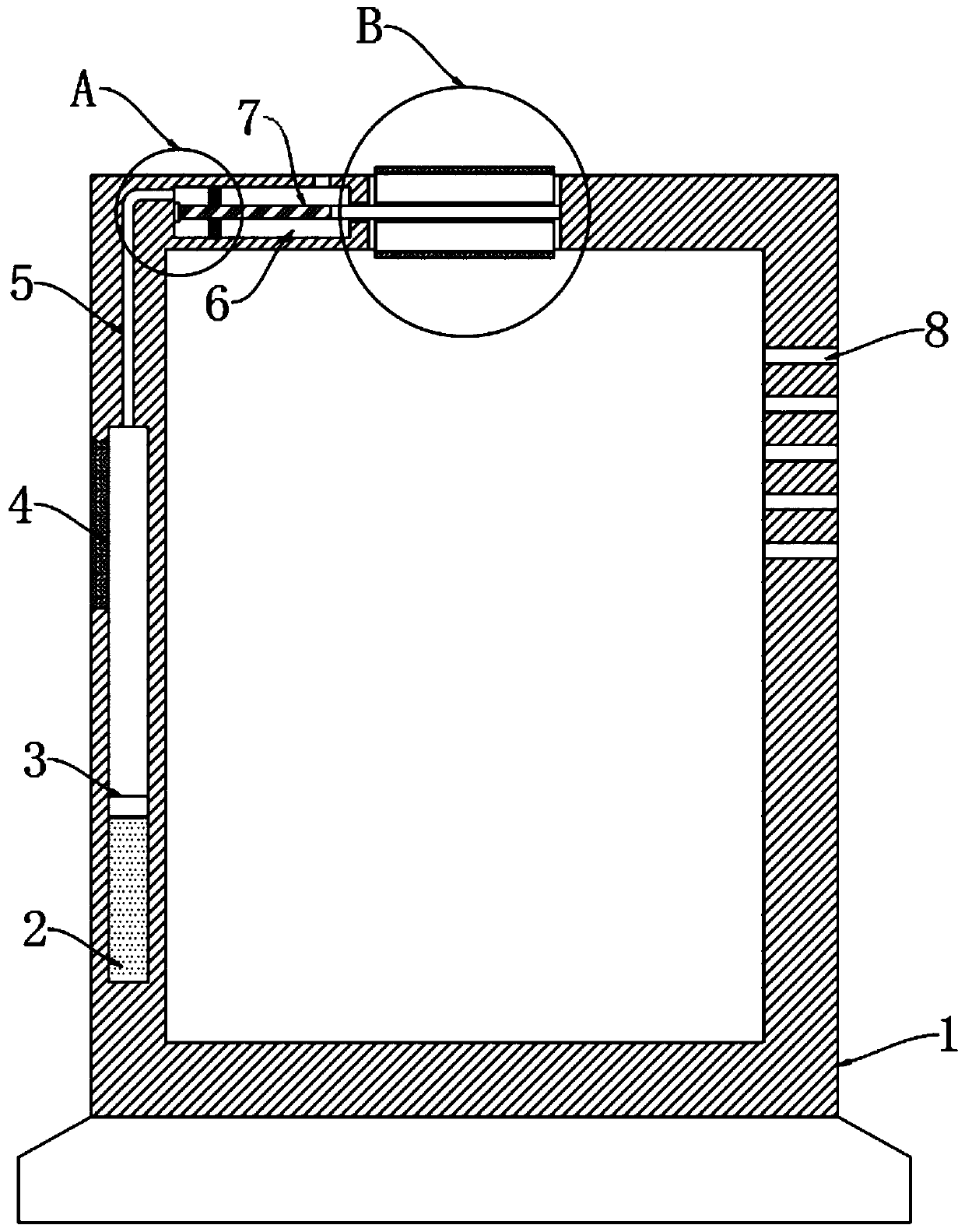
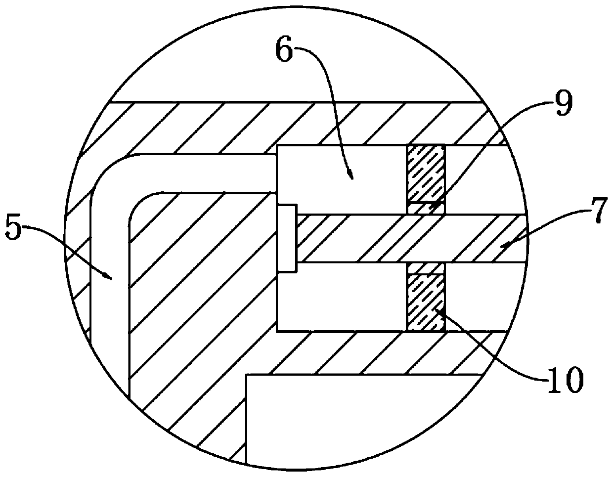
[0024] refer to Figure 1-4 , a self-radiating power cabinet, including a cabinet body 1, a cavity 2 is provided in the side wall of the cabinet body 1, a sliding plug 3 is sealed and slidingly connected between the inner walls of the cavity 2, and the lower end of the cavity 2 and the sliding plug 3 The space is filled with evaporative liquid, and a heat conducting plate 4 is embedded at the upper end of the corresponding cavity 2 on the side wall of the cabinet body 1 .

[0025] Further, the evaporating liquid adopts trichloromethane, and the boiling point temperature of trichloromethane is 61°C-62°C, while the conventional working temperature of electrical components in the power cabinet is -20°C-60°C, so when the temperature in the cabinet 1 is too high When it is close to or even exceeds 60°C, the evaporating liquid starts to evaporate.

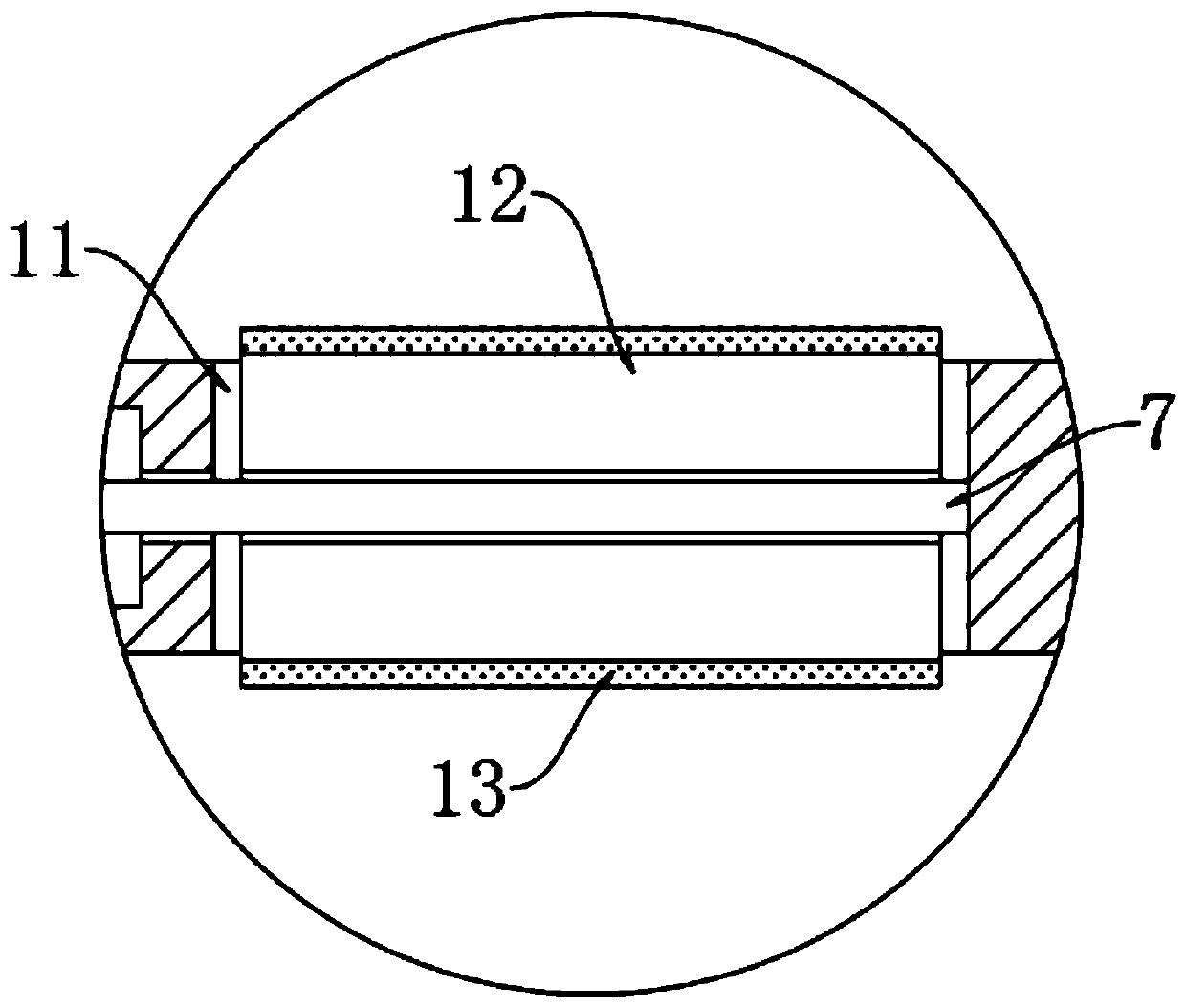
[0026] The upper side wall of the cabinet body 1 is provided with a rectangular installation opening 11, and the installation opening ...

Embodiment 2

[0035] refer to Figure 5-6The difference from Embodiment 1 is that: the top of the cabinet body 1 is provided with an air outlet hole 15 communicating with the end of each device chamber 6 near the installation port 11, and the air outlet hole 15 is equipped with a device that only allows air to flow from the inside of the cabinet body 1 to The one-way valve in the device cavity 6, the one-way valve that only allows air to flow from the device cavity 6 to the outside of the cabinet body 1 is installed in the vent hole 14 .

[0036] In this embodiment, when the annular sliding plug 10 slides to the left, negative pressure is generated in the device chamber 6, and the hot air in the cabinet 1 flows into the device chamber 6 from the air outlet 15. When the annular sliding plug 10 slides to the right , the hot air in the device cavity 6 is discharged from the vent hole 14, and the hot air in the cabinet body 1 can be continuously discharged with the continuous reciprocating slid...


PUM


Abstract

The invention discloses a self-heat-dissipation power cabinet which comprises a cabinet body, cavities are formed in side walls of the cabinet body, sliding plugs are connected between inner walls ofthe cavities in a sealed and sliding mode, the spaces between lower end portions of the cavities and the sliding plugs are filled with evaporation liquid, and heat conduction plates are embedded in the positions, corresponding to upper end portions of the cavities, of the side walls of the cabinet body. According to the invention, the evaporation liquid, a driving mechanism and a heat dissipationcolumn body are arranged; the evaporation liquid can be used to absorb heat emitted by electric appliance elements in the electric power cabinet body during work, therefore, the evaporated liquid is vaporized to push the sliding plugs to slide, gas is pushed into a device cavity, a rotating shaft is driven to rotate by taking air pressure as driving force; and meanwhile, the evaporated liquid is in direct contact with the heat conduction plate, the cooling and liquidation are achieved, the resetting of the heat dissipation cylinder is achieved, the heat dissipation is continuously conducted onthe electric appliance elements, and the auxiliary heat dissipation and cooling effect on the electric appliance elements can be achieved through exhausting and air suction of the device cavity.

Description

technical field [0001] The invention relates to the technical field of power equipment, in particular to a self-radiating power cabinet. Background technique [0002] The power cabinet is one of the most common and important equipment in the field of basic power facilities. Its function lies in the installation of circuits and power components. There are a large number of power components installed inside the power cabinet. [0003] The structure of various circuit components inside the power cabinet is relatively complex. When the electrical components in the power distribution cabinet are in high-load working conditions, a large amount of heat will be generated. If the heat is not dissipated in time, it will cause damage to the electrical components in the cabinet. Damage, which can cause the electrical appliances supplied by the power cabinet to be unable to use normally, and cause electrical safety accidents in severe cases. [0004] The heat dissipation device of the e...

Claims


Application Information

Patent Timeline
IPC IPC(8): H02B1/56H02B1/30
CPCH02B1/30H02B1/306H02B1/565
Inventor 胡从勇
Owner 胡从勇
Why Eureka
Try Eureka