Double-stroke separation type direct-acting solenoid valve

A separate, direct-acting technology, applied in the direction of valve lift, valve detail, valve device, etc., can solve the problems of reduced life of solenoid valve, seal failure, increased distance, etc., to achieve the effect of improving service life and avoiding excessive compression

Inactive Publication Date: 2020-06-30
行益科技(宁波)有限公司
View PDF5 Cites 1 Cited by
  • Summary
  • Abstract
  • Description
  • Claims
  • Application Information

AI Technical Summary

Problems solved by technology

In the traditional solenoid valve, one end of the moving iron core of the electromagnetic control device is inserted into the valve sleeve of the valve stem, that is, the valve sleeve is provided with a groove inward, and the end of the moving iron core is inserted into the groove. For valves with sealing material as the original sealing element, when the power is not energized for a long time, due to the spring force, the indentation on the gasket will gradually deepen with time, and the distance between the moving and static iron cores will gradually increase. After the critical distance is greater than the rated voltage, the iron core will not be able to pull in when the rated voltage is applied to the coil.
[0003] And because the service life of existing solenoid valves is generally about 50 million times, the sealing gasket on the valve stem will be fatigued and damaged due to the installation of 50 million times. Under the action of high-speed impact on the valve stem, the valve stem drives the gasket to impact the valve port together. Since all the moving parts are faster during the impact, they will continue to move under the drive of inertia. At this time, the gasket will be over-compressed and the gasket will be damaged. , resulting in sealing failure, which leads to a reduction in the life of the solenoid valve, so it is very important to obtain a double-stroke separate direct-acting solenoid valve that can greatly improve the service life

Method used


Image

  • Double-stroke separation type direct-acting solenoid valve
  • Double-stroke separation type direct-acting solenoid valve
  • Double-stroke separation type direct-acting solenoid valve

Examples


Embodiment 1

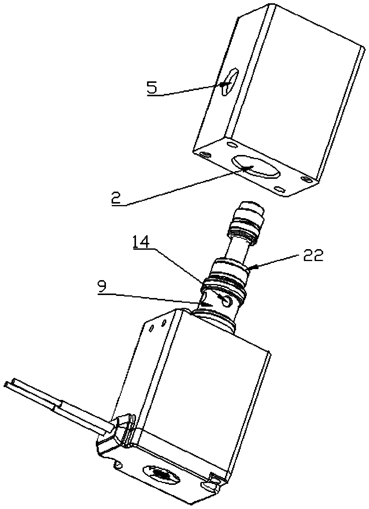
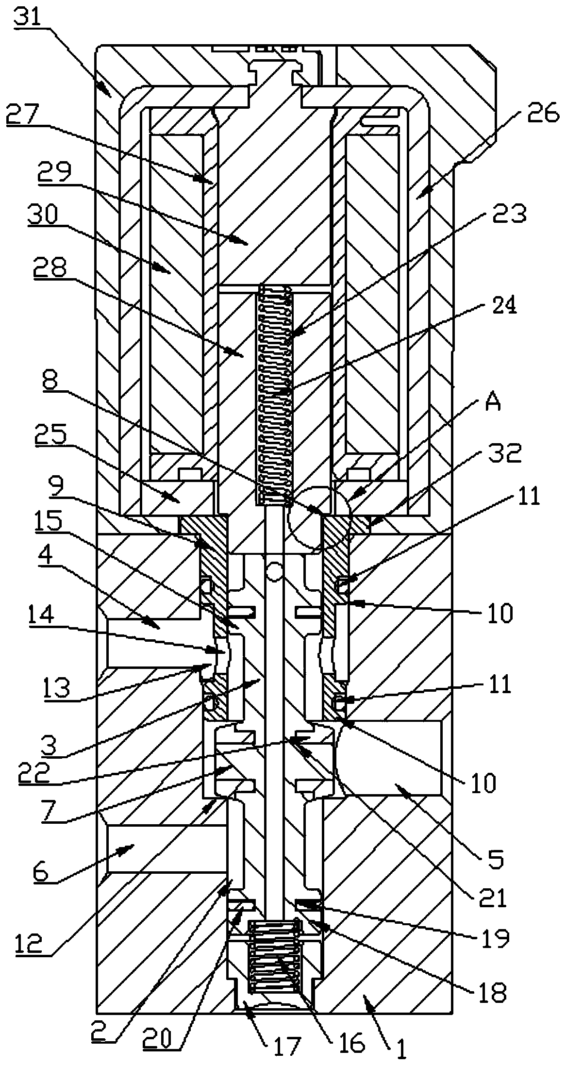
[0020] Embodiment 1: Referring to the accompanying drawings, the present invention adopts the following technical solution, a double-stroke separated direct-acting solenoid valve, including an electromagnetic control device and a valve body, characterized in that the valve body has a valve inner cavity, and the electromagnetic drive The device is installed at the opening end of the inner cavity of the valve; a valve stem is placed in the inner cavity of the valve, and the inner wall has a first channel, a second channel and a third channel; the valve stem is provided with a valve core, and the electromagnetic drive device controls the valve After the rod is displaced, the passage that connects the second passage with the third passage is blocked by the spool and disconnected, while the second passage communicates with the first passage, or the passage that connects the second passage with the first passage is blocked by the spool. Blocked and disconnected, the second channel co...

Embodiment 2

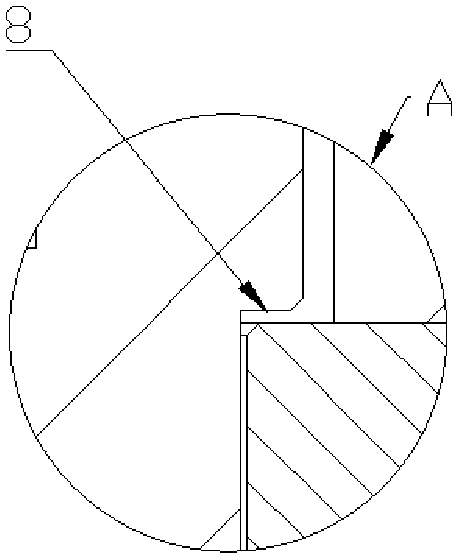
[0030] The difference between the present embodiment and the first embodiment is that the electromagnetic control device under the present embodiment includes: the second shell, the second magnetic plate embedded in the bottom of the second shell, and the second magnetic plate positioned in the inner cavity of the second shell. The two-shaped magnetic conductor, the I-shaped insulating cylinder two, the moving iron core two and the static iron core two, and the corresponding two side walls of the magnetic plate two are respectively in conflict with the inner surface of the bottom of the longitudinal part of the two-shaped magnetic conductor; The I-shaped insulating cylinder 2 is positioned in the inner cavity of the 冂-shaped magnetizer 2, the moving iron core 2 and the static iron core 2 located below the moving iron core 2 are positioned in the axial inner hole, and the radial outer peripheral side Coil 2 is wound, and the top of the moving iron core contacts with the top side...


PUM


Abstract

The invention discloses a double-stroke separation type direct-acting solenoid valve, which comprises an electromagnetic control device and a valve body, wherein a valve rod is arranged in the valve body; the inner side wall of the valve body is provided with a first channel, a second channel and a third channel; the valve rod is provided with a valve element; after an electromagnetic driving device controls the valve rod to generate displacement, the channels are controlled to be connected or disconnected; a junction of a first movable iron core and the valve bush of the valve rod is providedwith a spacing step, i.e., the top inner wall of the valve bush is in contact with the bottom of the first movable iron core; in addition, a concave table positioned on the bottom of the first movable iron core is used for spacing; and after the bottom end of the first movable iron core penetrates through the through hole of a first magnetic conduction plate, the bottom end of the first movable iron core is abutted against the top end of the valve rod in the valve bush so as to avoid a phenomenon that the electrified iron core can not be attracted. The spacing step restricts a distance between the first movable iron core and a first static iron core to be in a critical distance all the time, and in addition, a certain amount of compression of a sealing gasket is still compressed on a valve hole all the time to guarantee sealing. The continuous movement of the first movable iron core under an inertia function is restricted, the working of the first movable iron core in a stroke is restricted, the sealing gasket prevents from being excessively compressed, and the service life is prolonged.

Description

technical field [0001] The invention relates to the technical field of electric control valves, in particular to a double-stroke separated direct-acting solenoid valve. Background technique [0002] Solenoid valve is an industrial equipment controlled by electromagnetic. It is an automatic basic component used to control fluid. It belongs to actuator and is not limited to hydraulic and pneumatic. It is used to adjust the direction, flow, speed and other parameters of the medium in the industrial control system. In the traditional solenoid valve, one end of the moving iron core of the electromagnetic control device is inserted into the valve sleeve of the valve stem, that is, the valve sleeve is provided with a groove inward, and the end of the moving iron core is inserted into the groove. For valves with sealing material as the original sealing element, when the power is not energized for a long time, due to the spring force, the indentation on the gasket will gradually dee...

Claims


Application Information

Patent Timeline
Patent Type & Authority Applications(China)
IPC IPC(8): F16K31/06F16K1/32
CPCF16K1/32F16K31/0627
Inventor 曾愉深芦成苏军坤郝思思
Owner 行益科技(宁波)有限公司
Why Eureka
Try Eureka