Electric tool

An electric tool and linkage technology, applied in the field of electric hair dryers, can solve the problems of complicated operation and inconvenience for users, and achieve the effect of convenient operation and convenient backhand operation.

Pending Publication Date: 2019-03-01
CHANGZHOU GLOBE CO LTD
View PDF0 Cites 2 Cited by
  • Summary
  • Abstract
  • Description
  • Claims
  • Application Information

AI Technical Summary

Problems solved by technology

[0003] In practical applications, users often need to limit the minimum speed of the motor and the minimum air output according to different applications. The existing electric hair dryer is provided with a knob on one side of the handle, and the user realizes the speed limit of the motor by rotating the knob. However, , when the user is accustomed to operating on the other side, such a design will bring inconvenience to the user; in addition, the acceleration function needs to be realized by operating another acceleration button, which makes the operation cumbersome

Method used


Image

  • Electric tool
  • Electric tool
  • Electric tool

Examples


Embodiment Construction

[0026] In order to make the object, technical solution and advantages of the present invention clearer, the present invention will be described in detail below in conjunction with the accompanying drawings and specific embodiments.

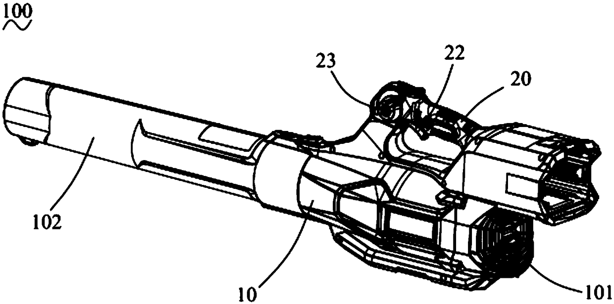
[0027] see figure 1 As shown, the present invention discloses a power tool 100, which is preferably a hair dryer. The electric tool 100 includes a housing 10 , a motor (not shown) accommodated in the housing 10 , and a handle 20 formed on the housing 10 . The housing 10 is provided with an air inlet 101 and an air outlet 102 . The motor is provided with fan blades (not shown), and the fan blades are driven by the motor to rotate, so as to suck air from the air inlet 101 and blow the air out from the air outlet pipe 102 .

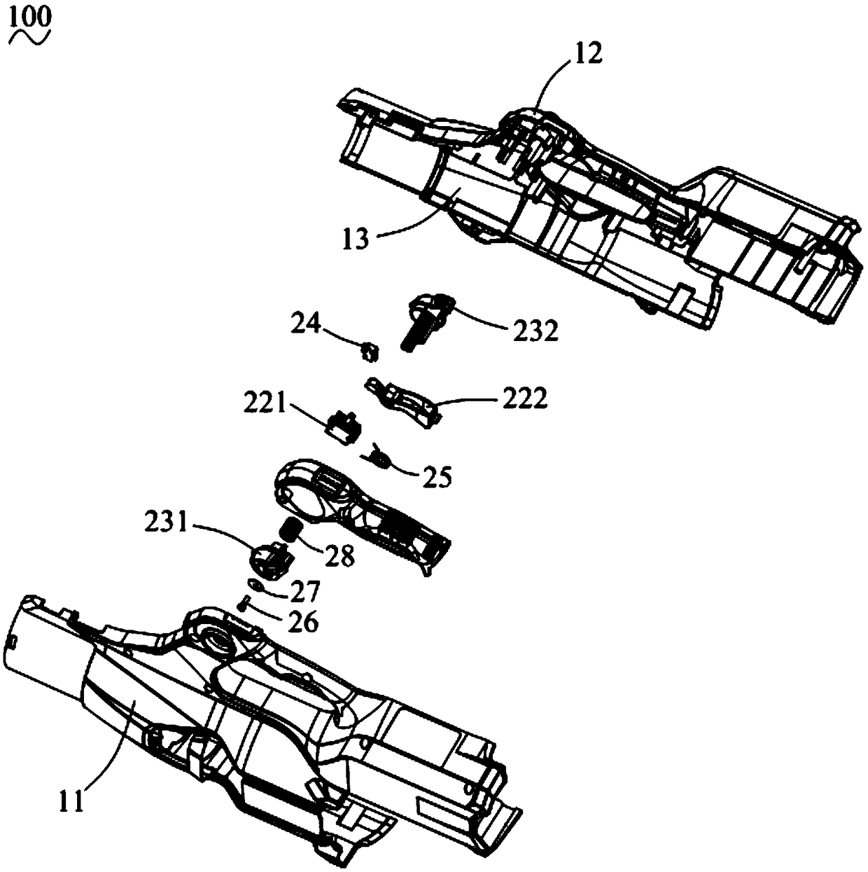
[0028] In the present invention, the handle 20 and the housing 10 are integrally formed, that is, the handle 20 belongs to a part of the housing 10; of course, in other embodiments, the handle 20 and the housing 10 can also be...


PUM


Abstract

The invention provides an electric tool. The tool includes a shell, a motor contained in the shell and a handle formed on the handle. A speed regulating mechanism for regulating the speed of the motoris arranged on the handle and a speed limiting mechanism matched with the speed regulating mechanism. The speed limiting mechanism comprises a first rotary knob and a second rotary knob arranged on the two sides of the handle respectively. The first rotary knob and the second rotary knob are connected to limit the motor to work at a fixed speed when the first rotary knob or the second rotary knobis moved. Compared with the prior art, the rotary knobs on the left and right sides of the handle can be adjusted, it is convenient for an operator to operate the tool backhand and operation is moreconvenient.

Description

technical field [0001] The invention relates to an electric tool, in particular to an electric hair dryer. Background technique [0002] The handle of existing electric blower is all provided with speed regulating mechanism, to regulate the rotating speed of motor. The speed regulating mechanism includes a speed regulating switch and a switch trigger matched with the speed regulating switch. The speed regulating switch has a pressing part, and the deeper the pressing stroke of the pressing part is, the higher the rotating speed of the motor is. The switch trigger is pivotally mounted on the handle . When the operator presses one end of the switch trigger, the other end of the switch trigger abuts against the pressing part, thereby adjusting the pressing stroke of the pressing part, thereby realizing the speed regulation of the motor. [0003] In practical applications, users often need to limit the minimum speed of the motor and the minimum air output according to differen...

Claims


Application Information

Patent Timeline
Patent Type & Authority Applications(China)
IPC IPC(8): A45D20/10A45D20/12
CPCA45D20/10A45D20/124B25F5/00H02K11/28B25F5/02H02K7/14
Inventor 上官云杰
Owner CHANGZHOU GLOBE CO LTD
Why Eureka
Try Eureka