
Gas turbine engine fan and nozzle geometry

A technology for gas turbines and exhaust nozzles, used in gas turbine installations, climate sustainability, jet propulsion, etc., to solve problems such as the unsuitability of engines to be installed under the wings and the impact of aircraft performance

Pending Publication Date: 2020-06-30
ROLLS ROYCE PLC
View PDF0 Cites 0 Cited by
  • Summary
  • Abstract
  • Description
  • Claims
  • Application Information

AI Technical Summary

Problems solved by technology

If parts of an engine are scaled - simply zooming in on a known engine type - the added drag could negatively affect the performance of the aircraft the engine is mounted on
Additionally or alternatively, the engine may not fit under the wing of the aircraft unless sized

Method used


Image

  • Gas turbine engine fan and nozzle geometry
  • Gas turbine engine fan and nozzle geometry
  • Gas turbine engine fan and nozzle geometry

Examples


Embodiment Construction

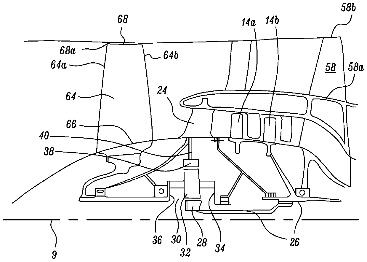
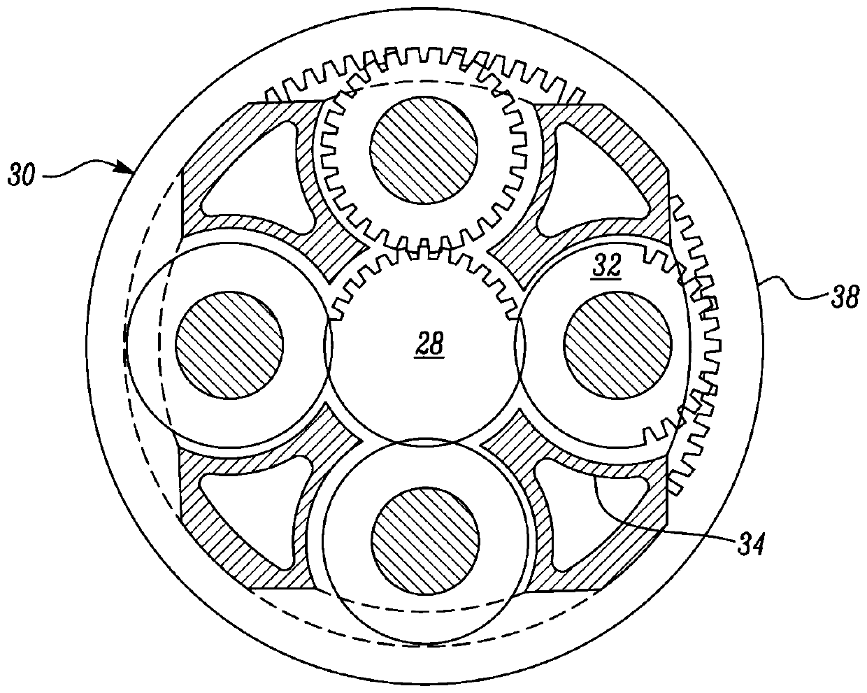
[0432] figure 1 A gas turbine engine 10 with a main axis of rotation 9 is shown. The engine 10 includes an air intake 12 and a propeller fan 23 that generates two airflows: a core airflow A and a bypass airflow B. The gas turbine engine 10 includes a core 11 receiving a core flow A. As shown in FIG. The engine core 11 includes a low-pressure compressor 14 , a high-pressure compressor 15 , a combustion device 16 , a high-pressure turbine 17 , a low-pressure turbine 19 and a core exhaust nozzle 20 in axial series. A nacelle 21 surrounds the gas turbine engine 10 and defines a bypass duct 22 and a bypass exhaust nozzle 18 . The bypass gas flow B flows through the bypass duct 22 . The fan 23 is attached to and driven by the low pressure turbine 19 via a shaft 26 and an epicyclic gearbox 30 .

[0433] In use, the core gas stream A is accelerated and compressed by the low pressure compressor 14 and directed into the high pressure compressor 15 for further compression. The compr...


PUM

PropertyMeasurementUnit
Radiusaaaaaaaaaa
Radiusaaaaaaaaaa
Angleaaaaaaaaaa

Abstract

The invention provides a gas turbine engine fan and a nozzle geometry. A gas turbine engine (10) for an aircraft comprises an engine core (11) comprising a turbine (19), a compressor (14 ), and a coreshaft (26) connecting the turbine to the compressor; a fan (23) located upstream of the engine core, the fan comprising a plurality of fan blades, wherein a fan tip radius (102) of the fan (23) is measured between a centreline of the engine (10) and an outermost tip (68) of each fan blade (64) at its leading edge (64a); and a nacelle (21) surrounding the fan (23) and the engine core (11) and defining a bypass exhaust nozzle (18), the bypass exhaust nozzle having an inner radius (116). The ratio of the inner bypass to the is in the range from 0.4 to 0.65.

Description

technical field [0001] The present disclosure relates to gas turbine engines for aircraft, and more particularly, to gas turbine engines having specified relative component dimensions. Background technique [0002] The skilled artisan will appreciate that simply scaling up components of a known engine type may not provide a corresponding scaling of power / thrust and / or efficiency, and may introduce issues such as increased drag or difficulty of installation. Therefore, it may be appropriate to reconsider the engine parameters. [0003] For example, the skilled artisan will appreciate that if the overall size of a gas turbine engine is increased, one problem that may need to be addressed is how to reduce the overall drag generated by the correspondingly larger nacelle of the larger engine in use. If parts of an engine are scaled—simply zooming in on a known engine type—the added drag could negatively affect the performance of the vehicle the engine is mounted on. Additionall...

Claims


Application Information

Patent Timeline
IPC IPC(8): F02C3/04F04D29/38F01D9/02F01D17/16
CPCF01D9/02F01D17/16F02C3/04F04D29/388F02C7/36F02K3/06F05D2260/40311Y02T50/60F02C3/073F02C9/18
Inventor 理查德·G·斯特雷顿迈克尔·C·威尔莫特
Owner ROLLS ROYCE PLC
Learn More