An anti-dump printing paper transfer tray
A printing paper and anti-dumping technology, which is applied in the direction of packaging, transportation, packaging, containers, etc., can solve the problems of tilting and falling, low work efficiency, printing paper is easy to tilt and fall, and achieve the effect of avoiding tilting and falling
- Summary
- Abstract
- Description
- Claims
- Application Information
AI Technical Summary
Problems solved by technology
Method used
Image
Examples
Embodiment 1
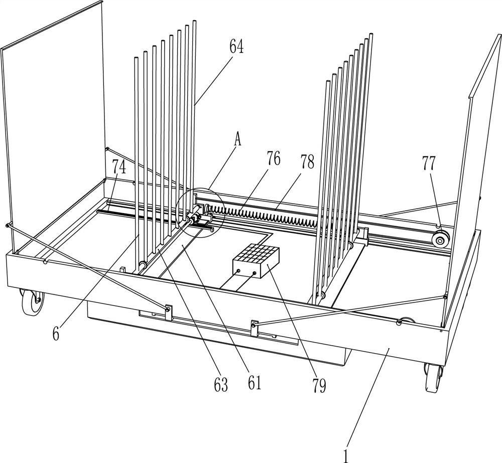
[0023] Such as figure 1 , figure 2 and image 3 As shown, an anti-dumping printing paper transfer tray includes a tray 1, a grid plate 2, a cover plate 3, a housing 4, an opening and closing mechanism 5 and a blocking mechanism 6, and the tops of the left and right sides of the tray 1 are hinged with covers. Plate 3, cover plate 3 cooperates with tray 1, and an opening and closing mechanism 5 is arranged between cover plate 3 and the outer bottom of tray 1, and shell 4 is installed on the bottom outside of tray 1, and opening and closing mechanism 5 is located in shell 4, and the tray A grid plate 2 is placed in the tray 1, and a blocking mechanism 6 that can block the printing paper is provided in the tray 1, and the blocking mechanism 6 cooperates with the grid plate 2.
[0024] The opening and closing mechanism 5 includes a cylinder 51, a movable slide rail 52, a movable slider 53, a rotating plate 54 and a connecting rod 55. The front and rear sides of the outer bottom ...
Embodiment 2
[0030] Such as Figure 5 and Figure 6 As shown, the main difference between this embodiment and embodiment 1 is that this embodiment also includes a moving mechanism 7, and the moving mechanism 7 includes a driving motor 71, a rotating shaft 72, a first gear 73, a rack 74, a limit Switch 75, spring 76, belt pulley 77, flat belt 78 and storage battery 79, the left side slide frame 61 front side rotation type is connected with rotating shaft 72, and the rear portion of rotating shaft 72 is fixedly connected with the first gear 73, the left side slide frame 61 rear portion The drive motor 71 is installed by means of bolt connection, the output shaft of the drive motor 71 is connected to the rear end of the rotating shaft 72 through a coupling, and a rack 74 is fixedly connected to the rear of the inner left side of the tray 1, and the rack 74 is located at the first gear. 73 meshes with it directly below, and the right part of the inner rear side of the tray 1 is connected with...
Embodiment 3
[0033] Such as Figure 4-Figure 7 As shown, the main difference between this embodiment and embodiment 1 and embodiment 2 is that in this embodiment, a second gear 8 and a tooth block 9 are also included, and the front and rear parts of the left and right rotating rods 63 are fixedly connected with the second gear. For the second gear 8, tooth blocks 9 that cooperate with the second gear 8 are installed symmetrically on the left and right sides of the bottom of the grid plate 2.
[0034] It also includes a pressing mechanism 10 and a universal wheel 11. The pressing mechanism 10 includes a pressing plate 101, a guide sleeve 102 and a third fastening bolt 103. The blocking rods 64 on the left and right sides are slidingly arranged to hold the printing paper. Compressed pressure plate 101, both sides of the top of pressure plate 101 are connected with guide sleeve 102, guide sleeve 102 cooperates with blocking rod 64, guide sleeve 102 is provided with third fastening bolt 103, a...
PUM
 Abstract
Description
Claims
Application Information
 - R&D
- Intellectual Property
- Life Sciences
- Materials
- Tech Scout
- Unparalleled Data Quality
- Higher Quality Content
- 60% Fewer Hallucinations
Browse by: Latest US Patents, China's latest patents, Technical Efficacy Thesaurus, Application Domain, Technology Topic, Popular Technical Reports.
© 2025 PatSnap. All rights reserved.Legal|Privacy policy|Modern Slavery Act Transparency Statement|Sitemap|About US| Contact US: help@patsnap.com


