Laser spot calibration platform

A technology for calibrating the platform and laser spot, applied in laser welding equipment, metal processing equipment, welding equipment, etc., can solve problems such as Y-direction position out-of-tolerance, laser welding surface failure of the roof of the car body, etc., to reduce errors and improve smooth movement Sexuality, the effect of fixed-point limit tilting and falling

Pending Publication Date: 2022-07-22
JIANGLING MOTORS
View PDF1 Cites 0 Cited by
  • Summary
  • Abstract
  • Description
  • Claims
  • Application Information

AI Technical Summary

Problems solved by technology

[0005] The purpose of the present invention is to provide a laser spot calibration platform to solve the problem that the Y-direction position of the laser welding spot calibration of the existing V362 vehicle roof is out of tolerance, which will easily lead to the failure of the laser welding surface of the vehicle body roof proposed in the background technology

Method used


Image

  • Laser spot calibration platform
  • Laser spot calibration platform
  • Laser spot calibration platform

Examples


Embodiment Construction

[0030] The technical solutions in the embodiments of the present invention will be clearly and completely described below with reference to the accompanying drawings in the embodiments of the present invention. Obviously, the described embodiments are only a part of the embodiments of the present invention, but not all of the embodiments.

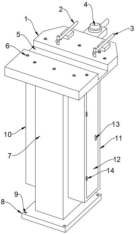
[0031] see Figure 1-5 , an embodiment provided by the present invention: a laser spot calibration platform, comprising: a placing platform 1, the upper end of the placing platform 1 is provided with a first clamping mechanism 2, and one side of the first clamping mechanism 2 is provided with a In the second clamping mechanism 3, the upper surface of the placing platform 1 is provided with a welding seam guide groove 5, and the welding seam guide groove 5 is integrated with the placing platform 1, and a supporting column 7 is provided below the placing platform 1;

[0032] Also includes:

[0033] The rotating column 15 is arranged at the l...


PUM


Abstract

The invention discloses a laser spot calibration platform, relates to the technical field of machining equipment, and aims to solve the problems that the Y-direction position of laser welding spot calibration of an existing V362 vehicle type top cover is out of tolerance, and a laser welding surface of a vehicle body top cover is easy to lose efficacy. A first clamping mechanism is arranged at the upper end of the placing platform, a second clamping mechanism is arranged on one side of the first clamping mechanism, a welding seam guide groove is formed in the upper surface of the placing platform, the welding seam guide groove and the placing platform are of an integrated structure, and a supporting column is arranged below the placing platform; the rotating column is arranged at the lower end of the placing platform, the rotating column and the placing platform are of an integrated structure, a rotating shaft is arranged at one end of the rotating column, and the rotating shaft and the rotating column are of an integrated structure; the electric push rod assemblies are arranged on the two sides of the supporting column, and adjusting columns are arranged at the upper ends of the electric push rod assemblies; and the moving column is arranged above the adjusting column.

Description

technical field [0001] The invention relates to the technical field of mechanical processing equipment, in particular to a laser spot calibration platform. Background technique [0002] In the V362 model roof laser welding equipment, the laser head needs to perform spot calibration on the lap welding seam of the body roof. Since the roof technology profile is an inclined surface structure, the calibration of the spot accuracy is relatively strict. Most of the laser heads are adjusted to adjust the spot. calibration; [0003] For example, the Chinese authorized patent with the announcement number of CN214489227U (a laser spot adjustable platform welding head) includes an optical fiber head connection seat, the inner wall of the optical fiber head connection seat is fixedly connected with a main body, and the upper surface of the main body is fixedly connected with an upper A protective mirror seat, a lower protective mirror seat is fixedly connected under the main body, an a...

Claims


Application Information

Patent Timeline
Patent Type & Authority Applications(China)
IPC IPC(8): B23K26/042
CPCB23K26/042B23K2101/006
Inventor 曾祥宗涂中炜黄志吴涛
Owner JIANGLING MOTORS
Why Eureka
Try Eureka