Punching and film attaching device

A film sticking device and material punching technology, which is applied in the field of 3C and semiconductor automatic film sticking, can solve the problems of easy occurrence of three injuries, inaccurate product and film position positioning, cumbersome steps, etc., and achieve the effect of avoiding three injuries

Inactive Publication Date: 2020-06-30
TZTEK TECH
View PDF5 Cites 0 Cited by
  • Summary
  • Abstract
  • Description
  • Claims
  • Application Information

AI Technical Summary

Problems solved by technology

Traditional manual film sticking steps are cumbersome and inefficient, greatly occupying human resources and cannot guarantee high-quality production
From product positioning to film release, there are various hidden dangers and deficiencies. For example, product positioning cannot be guaranteed in all directions, up, down, left, and right, and the same is true for the position of the film.
In addition, the accuracy of the film sticking process cannot be effectively controlled, and when the position of the film and the product cannot be accurately aligned, the film and the product will be prone to three injuries.
[0003] In addition, although semi-automatic punching and film sticking devices have appeared on the market, after stamping and pasting a product, it is necessary to reset the stamping part, and then drive the stamping part to perform a second stamping, which cannot achieve reciprocating Continuous stamping cannot be used for assembly line operations, which greatly reduces the efficiency of stamping and film application
However, the existing semi-automatic punching and film sticking device also has the defects of inaccurate product and film position positioning, and prone to three injuries during the stamping and film sticking process.

Method used


Image

  • Punching and film attaching device
  • Punching and film attaching device
  • Punching and film attaching device

Examples


Embodiment Construction

[0025] The present invention will be described in detail below in conjunction with various embodiments shown in the drawings. However, these embodiments do not limit the present invention, and structural, method, or functional changes made by those skilled in the art according to these embodiments are included in the protection scope of the present invention.

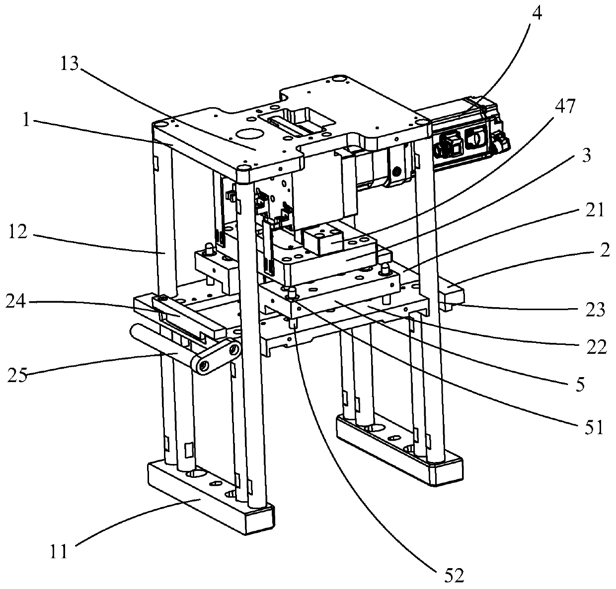
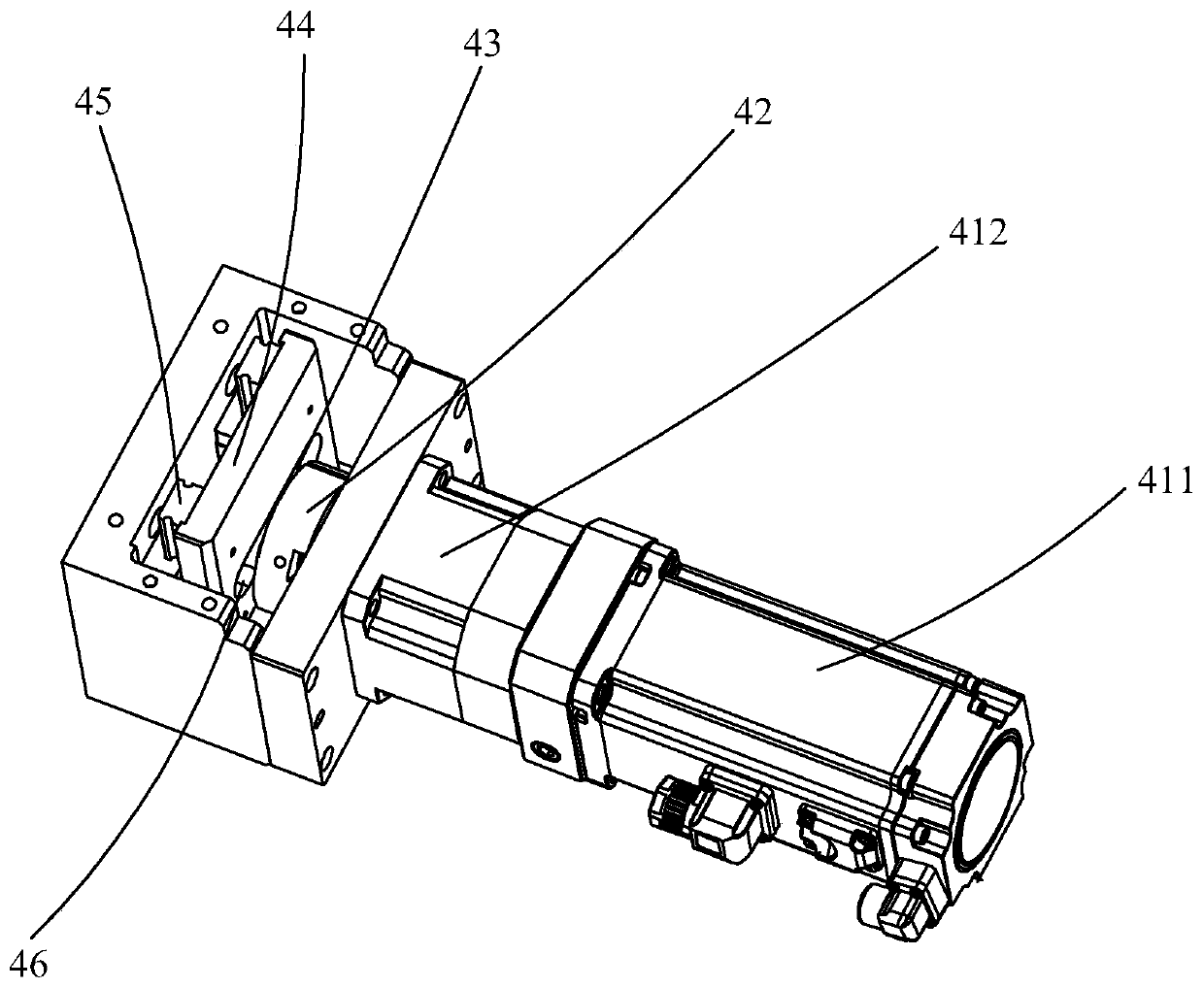
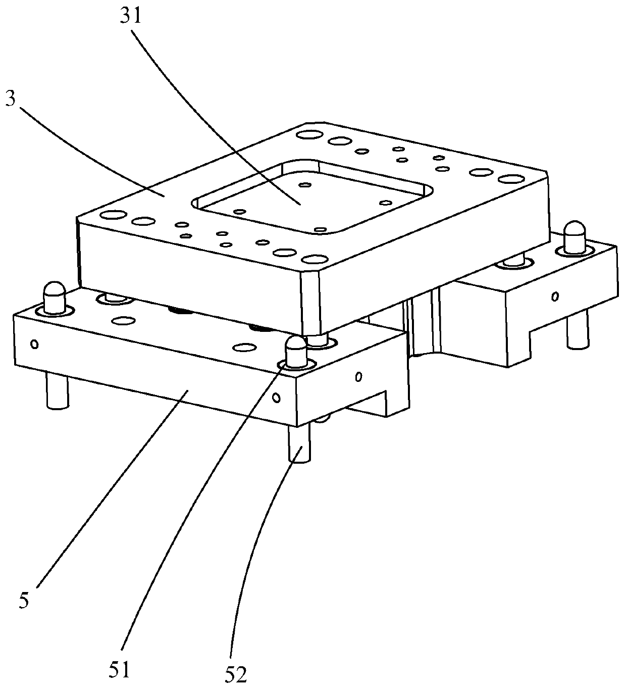
[0026] This embodiment provides a punching material film sticking device 100, including a base 1, a punching plate 2 fixed on the base 1, a punching push plate 3, and a driving mechanism 4, and the punching push plate 3 is arranged on the punching plate On the top of the template 2, the driving mechanism 4 is arranged above the punching push plate 3, and is used to drive the punching push plate 3 to press down to complete the film application. The driving mechanism 4 includes a driving source 41 protruding from one end of the driving source 41 The driving shaft 42 is provided with an eccentric device 43 at the end of th...


PUM


Abstract

The invention provides a punching and film attaching device which comprises a base, a punching template fixed to the base, a punching push plate and a driving mechanism. The punching push plate is arranged on the upper side of the punching template. The driving mechanism is arranged on the upper side of the punching push plate and used for driving the punching push plate to press down to completefilm attaching. The driving mechanism comprises a driving source and a driving shaft protruding and extending out of one end of the driving source. The tail end of the driving shaft is provided with an eccentric device. The driving mechanism further comprises a driving plate for reciprocating in cooperation with the eccentric device and a guide rail for bearing the reciprocating of the driving plate. The punching template is driven by a servo motor and a gear motor to move up and down on the guide rail, so that precise punching and film attaching operation is completed; the punching and film attaching device is stable and efficient and is widely applied the field of product punching and film attaching in the electronics industry, and semiconductor industry and other industries; and in addition, when the film attaching process is carried out through the punching and film attaching device, the three types of damage (scratch damage, collision damage and crush damage) to a film and a product can be effectively avoided.

Description

technical field [0001] The invention belongs to the field of 3C and semiconductor automatic film sticking, and in particular relates to a stamping film sticking device. Background technique [0002] In the existing semiconductor and 3C technology fields, it is often necessary to paste a protective film on the surface of the product. The traditional manual film sticking steps are cumbersome and inefficient, greatly occupying human resources and cannot guarantee high-quality production. From product positioning to film release, there are various hidden dangers and deficiencies. For example, product positioning cannot be guaranteed in all directions, up, down, left, and right, and the same is true for the position of the film. In addition, the accuracy of the film sticking process cannot be effectively controlled, and when the position of the film and the product cannot be accurately aligned, the film and the product are prone to three injuries. [0003] In addition, although...

Claims


Application Information

Patent Timeline
Patent Type & Authority Applications(China)
IPC IPC(8): B29C63/02B29L31/34
CPCB29C63/02B29L2031/34
Inventor 胡辉来马波闻刘勇曹葵康蔡雄飞徐一华
Owner TZTEK TECH
Why Eureka
Try Eureka