
Electric connection structure and connector thereof

A technology of electrical connection structure and connector, applied in the direction of connection, components and circuits of connecting devices, can solve the problem of limited screw connection structure settings, and achieve the effect of electric field optimization, optimization of electric field, and avoidance of influence

Inactive Publication Date: 2020-06-26
PINGGAO GRP +1
View PDF10 Cites 3 Cited by
  • Summary
  • Abstract
  • Description
  • Claims
  • Application Information

AI Technical Summary

Problems solved by technology

[0005] The purpose of the present invention is to provide an electrical connection structure, which is used to solve the problem that the setting of the screw connection structure is limited when the shielding cover of the existing electrical connection structure is fixed by screws; the present invention also provides a connector for Solve the problem that the setting of the screw connection structure is limited when the shielding cover on the existing connection head is fixed by screws

Method used


Image

  • Electric connection structure and connector thereof
  • Electric connection structure and connector thereof

Examples


Embodiment 2

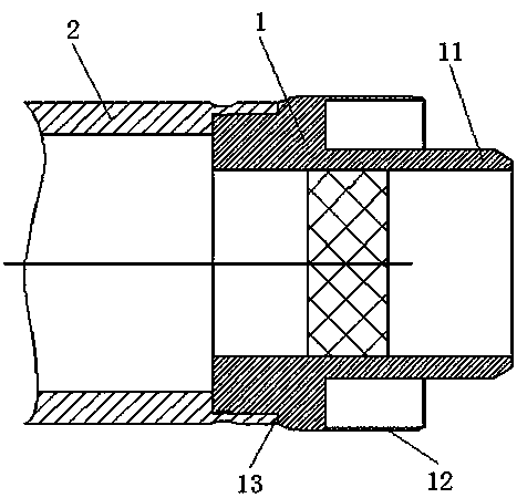
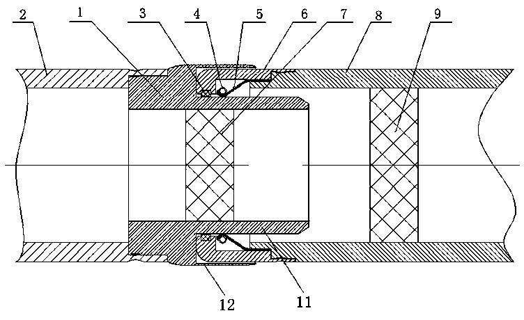
[0046] Embodiment 2 of the connector of the present invention. The difference between this embodiment and Embodiment 1 of the connector is that in Embodiment 1, the cylindrical shielding structure is a straight cylinder. In this embodiment, the cylindrical shielding structure has The arc-shaped barrel structure has a more arc-shaped transition shape, which can optimize the electric field of the connector.

Embodiment 3

[0047] Embodiment 3 of the connector of the present invention, the difference between this embodiment and Embodiment 1 of the connector is that, in Embodiment 1, the end of the conductive rod at the connector end is sleeved on the connecting step of the connector, and the two In this embodiment, the end face of the conductive rod at the connecting head end is abutted with the end face of the connecting head, and the conductive rod at the connecting head end is welded together with the connecting head.

Embodiment 4

[0048] Embodiment 4 of the connector of the present invention, the difference between this embodiment and Embodiment 1 of the connector is that in Embodiment 1, the connector is formed by cutting from a forging, and in this embodiment, the connector is made of a tubular The profile is formed by cutting.


PUM


Abstract

The invention relates to an electric connection structure and a connector thereof, and the electric connection structure comprises the connector and a connecting seat; the connector is provided with aconductive plugging part, and the conductive plugging part is used for being plugged into a conductive plugging hole in the connecting seat; the connector is fixedly provided with a shielding cover,and the connector is provided with a cylindrical shielding structure, wherein the cylindrical shielding structure is located at the radial outer side of the conductive plugging part and is coaxially arranged with the conductive plugging part; the cylindrical shielding structure and the main body part of the connector are integrally formed, an overhanging structure is formed on the main body part of the connector, and an annular space between the cylindrical shielding structure and the conductive plugging part forms an avoidance interval for avoiding the hole wall of the conductive plugging hole; the shielding cover is formed by a cylindrical shielding structure; the cylindrical shielding structure and the main body part of the connector are integrally formed, so a mounting space for assembling a screw is prevented from being reserved on the connector, the influence of the screw on the electric field of the electric connection structure is avoided, and the arrangement of the shielding cover in the electric connection structure is not limited by the screw connection structure.

Description

technical field [0001] The invention belongs to the field of electrical connection structures, and in particular relates to electrical connection structures and connectors thereof. Background technique [0002] The electrical connection structure is a widely used component in gas-insulated metal-enclosed switches (GIS) and gas-insulated metal-enclosed transmission lines (GIL). Its main function is to conduct rated current and instantaneous fault current in the main circuit. The quality of the electrical connection structure The quality directly affects the reliability of the equipment and the safe operation of the power grid. [0003] The electrical connection structure includes a connecting head and a connecting seat. Generally, one end of the connecting head is inserted into the corresponding end of the connecting seat when used, and the other end of the connecting head and the connecting seat is used to connect the corresponding conductive rod, so as to connect and conduc...

Claims


Application Information

Patent Timeline
IPC IPC(8): H01R13/6585H01R13/50
CPCH01R13/50H01R13/6585
Inventor 王红超李凯李艳洁徐仲勋宋继光李新刚司晓闯许东杰尹世献
Owner PINGGAO GRP
Learn More