Eureka AIR delivers breakthrough ideas for toughest innovation challenges, trusted by R&D personnel around the world.

Surface superfluous dimension machining removing mechanism adopted during installation of steel structure connecting piece

A connecting piece and steel structure technology, which is applied in the field of surface excess dimension processing and planing mechanism, can solve the problems of slow removal effect, affecting the docking effect, and insufficient levelness of the removed parts, so as to achieve firm fixation, improve the planing effect, and enhance the grinding effect. Effect

Active Publication Date: 2020-06-26
杭州富阳东顺钢结构有限公司
View PDF6 Cites 2 Cited by
  • Summary
  • Abstract
  • Description
  • Claims
  • Application Information

AI Technical Summary

Problems solved by technology

[0004] The object of the present invention is to provide a mechanism for processing and removing excess dimensions on the surface of steel structure connectors during installation, so as to solve the problem that the existing steel structure connectors proposed in the background technology usually use The grinding machine removes the problem that the removal part is not even enough, which affects the docking effect, and the removal effect is too slow

Method used


Image

  • Surface superfluous dimension machining removing mechanism adopted during installation of steel structure connecting piece
  • Surface superfluous dimension machining removing mechanism adopted during installation of steel structure connecting piece
  • Surface superfluous dimension machining removing mechanism adopted during installation of steel structure connecting piece

Examples


Embodiment Construction

[0032] The following will clearly and completely describe the technical solutions in the embodiments of the present invention with reference to the accompanying drawings in the embodiments of the present invention. Obviously, the described embodiments are only some, not all, embodiments of the present invention. Based on the embodiments of the present invention, all other embodiments obtained by persons of ordinary skill in the art without making creative efforts belong to the protection scope of the present invention.

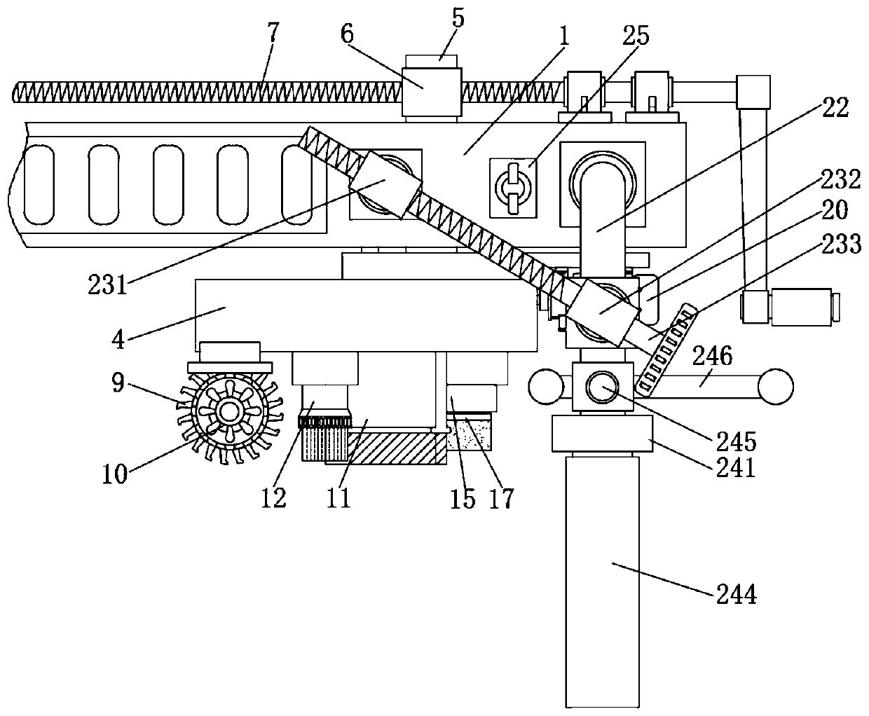
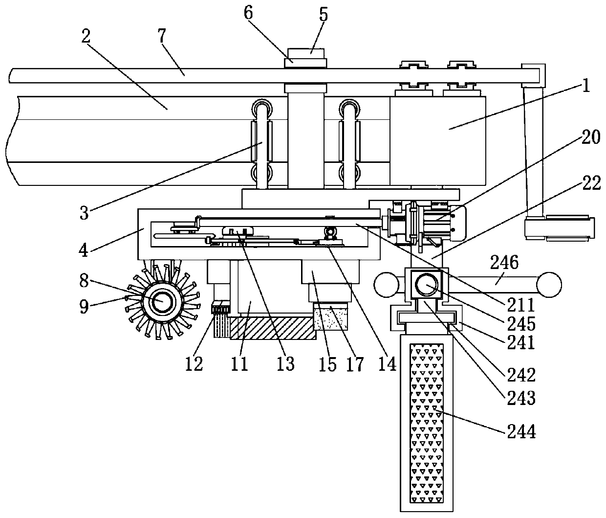
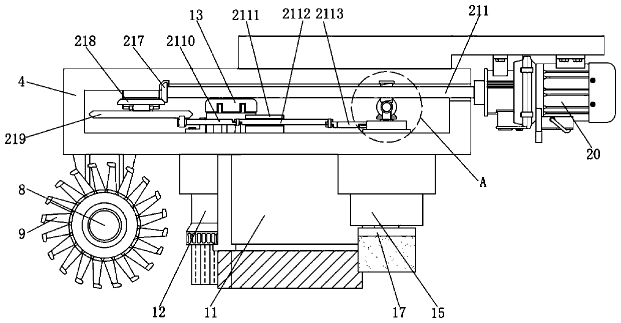
[0033] see Figure 1-11 , an embodiment provided by the present invention:

[0034] A surface excess dimension processing and planing mechanism for steel structure connector installation, including a beam 1, a first motor 10, a second motor 13, a third motor 20 and a control switch 25, a slide rail 2 is provided inside the beam 1, and The inside of the slide rail 2 is inlaid with two sets of connecting frames 3, and the bottom of the two sets of connecting fr...


PUM


Abstract

The invention discloses a surface superfluous dimension machining removing mechanism adopted during installation of a steel structure connecting piece. The mechanism comprises a beam, a first motor, asecond motor, a third motor and a control switch. A sliding rail is formed inside the beam. Two sets of connecting frames are embedded inside the sliding rail. An equipment box is welded to the bottoms of the two sets of connecting frames. A connecting rod is fixedly installed at the middle above the equipment box. A first screw is fixedly welded to the upper end of the connecting rod. The firstscrew is hinged to the portion above the beam through a support. A first rotating shaft is inserted at the left end of the bottom of the equipment box through a support. The connecting frame is installed in the sliding rail inside the beam, by means of a roller sleeving the connecting frame, the connecting frame can drive the equipment box to move straightly along the sliding rail, the machined surface removal smoothness of the device when in use is effectively improved, it is ensured that the removal plane is flat and straight, and the superfluous part of the connecting piece can be removed conveniently for butt-joint use.

Description

technical field [0001] The invention relates to the technical field of processing equipment for steel structure connectors, in particular to a mechanism for processing and removing redundant dimensions on the surface of steel structure connectors during installation. Background technique [0002] Steel structure connectors refer to specially made T-shaped or L-shaped steel materials with bolts, rivets and other steel structure equipment for fixed connection between multiple objects. Because the steel structure connectors are convenient to use, the connection between objects is stable. Therefore, it is widely used in the connection and fixation between various building frames. [0003] Because the existing steel structure connectors are uniformly formulated, they have the same specifications when used, so they cannot perfectly fit the connection gap between objects on the site. In field use, it is usually necessary to adjust the steel structure connectors. Grinding is carrie...

Claims


Application Information

Patent Timeline
Patent Type & Authority Applications(China)
IPC IPC(8): B23D1/08B23D7/00B23D7/06B23P23/04
CPCB23D1/08B23D7/00B23D7/06B23P23/04
Inventor 任永红李万青张萌萌
Owner 杭州富阳东顺钢结构有限公司
Why Eureka
Eureka Blog
Learn More