Lathe machining cutting device for hollow slender shaft

A lathe processing and cutting device technology, applied in the direction of turning equipment, positioning devices, feeding devices, etc., can solve the problems of machining and cutting errors, workpiece jumping, easy rotation and shaking, etc., and achieve the effect of improving precision

Inactive Publication Date: 2020-06-26
PUJIANG JISHU MASCH TECH CO LTD
View PDF0 Cites 3 Cited by
  • Summary
  • Abstract
  • Description
  • Claims
  • Application Information

AI Technical Summary

Problems solved by technology

[0003] The method of workpiece rotation and turning tool feed is generally suitable for processing short-distance workpieces. The hollow and slender shaft is too long, so it is very easy to rotate and shake when the lathe is cutting, and it is easy to happen when the turning tool touches The workpiece jumps. In addition, because the shaft is hollow, it is difficult to locate the device on the opposite side of the lathe fixture for workpiece positioning. There are also some fixtures for auxiliary lathe machining long axes on the market, but this type of clamping is usually only used on two or three sides. The type splint is clamped by soft contact, and the shaft is easy to rub against the splint when it is being processed and rotated, which will still cause machining and cutting errors.

Method used


Image

  • Lathe machining cutting device for hollow slender shaft
  • Lathe machining cutting device for hollow slender shaft
  • Lathe machining cutting device for hollow slender shaft

Examples


Embodiment Construction

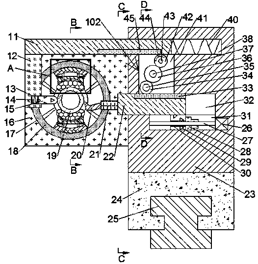
[0018] Combine below Figure 1-6 The present invention is described in detail, and for convenience of description, the orientations mentioned below are now stipulated as follows: figure 1 The up, down, left, right, front and back directions of the projection relationship itself are the same.

[0019] refer to Figure 1-6 , according to an embodiment of the present invention, a lathe machining and cutting device for a hollow slender shaft includes a control body 23, an electric sliding sleeve 24 is fixed on the bottom surface of the control body 23, and the electric sliding sleeve 24 slides forward and backward Located on the top surface of the slide rail 25, the control body 23 is provided with a connecting cavity 60 opening to the left, a moving cavity 38 and a sliding cavity 32, and the moving cavity 38 and the sliding cavity 32 are located in the connecting cavity 60 front side, the moving cavity 38 is located on the upper side of the sliding cavity 32, and two vertically...


PUM


Abstract

The invention discloses a lathe machining cutting device for a hollow slender shaft. The lathe machining cutting device comprises a control body, wherein an electric sliding sleeve is fixedly arrangedon the bottom surface of the control body, the electric sliding sleeve is arranged on the top surface of a sliding rail in a front-back sliding mode, a connecting cavity with a leftward opening, a moving cavity and a sliding cavity are formed in the control body, the moving cavity and the sliding cavity are located on the front side of the connecting cavity, the moving cavity is located on the upper side of the sliding cavity, and two sliding columns symmetrical up and down are fixedly arranged between the front wall and the rear wall of the connecting cavity. The lathe machining cutting device adopts a mode of middle stable positioning and clamping and along-shaft rotating to solve the problems that when a hollow shaft workpiece is machined by a lathe, the side of the lathe cannot be positioned in the circle center, due to too long length, rotating shaking is caused, and due to too long length, the jumping error is too large during cutting, and can effectively improve the precision during hollow shaft workpiece lathe cutting machining.

Description

technical field [0001] The invention relates to the technical field of lathe processing, in particular to a lathe processing cutting device for hollow elongated shafts. Background technique [0002] Lathe processing is a part of mechanical processing. There are two main processing forms: one is to fix the turning tool to process the unformed workpiece during rotation; the other is to fix the workpiece, and through the high-speed rotation of the workpiece, the lateral and Longitudinal movement for precision machining; [0003] The method of workpiece rotation and turning tool feed is generally suitable for processing short-distance workpieces. The hollow and slender shaft is too long, so it is very easy to rotate and shake when the lathe is cutting, and it is easy to happen when the turning tool touches The workpiece jumps. In addition, because the shaft is hollow, it is difficult to locate the device on the opposite side of the lathe fixture for workpiece positioning. There...

Claims


Application Information

Patent Timeline
Patent Type & Authority Applications(China)
IPC IPC(8): B23B5/08B23B25/00B23B27/00B23Q3/00B23Q5/28
CPCB23B5/08B23B25/00B23B27/00B23Q3/00B23Q5/28
Inventor 沈露霞
Owner PUJIANG JISHU MASCH TECH CO LTD
Why Eureka
Try Eureka