
A solar photovoltaic power supply monitoring system

A solar photovoltaic and power monitoring technology, applied in the monitoring of photovoltaic systems, photovoltaic power generation, photovoltaic modules, etc., can solve the problems of lack of monitoring, failures are not easy to be found, affecting the normal operation of the working scene, etc., to ensure normal operation and normal operation. running effect

Active Publication Date: 2021-04-06
三河益生电子科技开发有限公司
View PDF5 Cites 0 Cited by
  • Summary
  • Abstract
  • Description
  • Claims
  • Application Information

AI Technical Summary

Problems solved by technology

[0003] Especially for remote areas where there is no mains power supply (such as natural gas pipeline monitoring stations in remote areas), it is the preferred power supply solution to combine generators and photovoltaic power generation systems; Make the fault difficult to be found and affect the normal work of the above working scenarios

Method used


Image

  • A solar photovoltaic power supply monitoring system
  • A solar photovoltaic power supply monitoring system
  • A solar photovoltaic power supply monitoring system

Examples


Embodiment 1

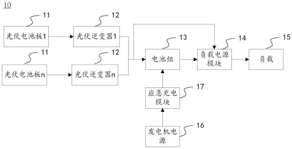
[0042] This embodiment provides a solar photovoltaic power supply monitoring system for monitoring solar photovoltaic power generation systems; figure 1 As shown, the solar photovoltaic power generation system 10 includes several photovoltaic panels 11, a photovoltaic inverter 12 corresponding to each photovoltaic panel 11, and a battery pack 13, wherein the battery pack 13 is composed of several individual batteries; the photovoltaic inverter The converter 12 is used to charge the battery pack 13 after converting the power supply of the photovoltaic panel 11 into direct current; the battery pack 13 and / or the photovoltaic inverter 12 is used to supply power to the load 15 through the load power supply module 14; In this embodiment, the solar photovoltaic power generation system 10 also includes a module for charging the battery pack 13 through the generator power supply 16 and the emergency charging module 17 for emergency use. Wherein, the generator power supply 16 can be a ...

Embodiment 2

[0082] On the basis of Example 1, such as image 3As shown, the monitoring system provided by this embodiment also includes a protection device 40 for placing the tablet computer (that is, the monitoring host 21), and the protection device 40 includes a base 41 with an open side, and the base 41 The middle part forms a placement cavity 42 for placing a tablet computer (that is, the monitoring host 21); the placement cavity 42 is an inclined cavity with an opening higher than the bottom surface; a U-shaped installation for clamping a tablet computer is placed in the placement cavity plate 43; the side of the mounting plate 43 away from the tablet computer is provided with a pull rod 43-1 protruding from the base;

[0083] The middle part of the placement cavity 42 can be inserted with a first-level sealing plate 44 slidingly up and down; the opening top of the placement cavity is hinged with a second-level sealing plate 45; the outer end of the first-level sealing plate 44 is f...


PUM


Abstract

The application provides a solar photovoltaic power supply monitoring system, including a monitoring host, a programmable controller, a sensor component and a monitoring power supply module; the monitoring host has a touch screen; the programmable controller is connected to an expansion module through a parallel bus; the sensor component includes a photovoltaic voltage sensor , battery pack voltage sensor, load voltage sensor, temperature sensor, current sensor; the sensor component transmits the detected signal to the programmable controller or its expansion module; the monitoring host receives all the signals through the programmable controller and displays them on the on the touch screen. This application monitors the parameters such as voltage, current and temperature in the solar photovoltaic power generation system through the monitoring host and programmable controller, and displays them on the touch screen, and can automatically and selectively turn on the power supply of the generator according to the power generation of the photovoltaic panel. So as to ensure the normal operation of the battery pack and the normal operation of the solar photovoltaic power generation system.

Description

technical field [0001] The present application relates to the technical field of solar power generation monitoring technology, in particular to a solar photovoltaic power monitoring system. Background technique [0002] Photovoltaic power generation is based on the principle of photovoltaic effect, using solar cells to directly convert sunlight energy into electrical energy. Regardless of whether it is used independently or connected to the grid for power generation, the photovoltaic power generation system is mainly composed of three parts: solar panels (components), controllers and inverters. They are mainly composed of electronic components and do not involve mechanical parts. Therefore, photovoltaic power generation equipment Extremely refined, reliable, stable, long life, easy to install and maintain. [0003] Especially for remote areas where there is no mains power supply (such as natural gas pipeline monitoring stations in remote areas), it is the preferred power su...

Claims


Application Information

Patent Timeline
Patent Type & Authority Patents(China)
IPC IPC(8): H02S50/00H02J9/08H02J7/00
CPCH02J7/0068H02J9/08H02S50/00Y02B10/70Y02E10/56
Inventor 王生赵德朝
Owner 三河益生电子科技开发有限公司
Learn More