
Three-phase dry-type isolation transformer

A technology for isolating transformers and dry-type transformers, applied in the field of transformers, can solve problems such as damage to dry-type transformers, inconvenient maintenance of dry-type transformers, rigid collision between dry-type transformers and isolation boxes, etc., to prolong the service life and improve the firmness of placement Effect

Inactive Publication Date: 2020-06-23
李元飞
View PDF0 Cites 0 Cited by
  • Summary
  • Abstract
  • Description
  • Claims
  • Application Information

AI Technical Summary

Problems solved by technology

[0003] The transformer is installed in the isolation box. Due to the limited space of the isolation box, when the dry-type transformer is installed in the isolation box, the dry-type transformer cannot be placed horizontally due to manual installation, which will cause rigid collision between the dry-type transformer and the isolation box. , which can easily lead to damage to the dry-type transformer. At the same time, the dry-type transformer is installed in the isolation box, and it is extremely inconvenient to repair the dry-type transformer.

Method used


Image

  • Three-phase dry-type isolation transformer
  • Three-phase dry-type isolation transformer
  • Three-phase dry-type isolation transformer

Examples


Embodiment 1

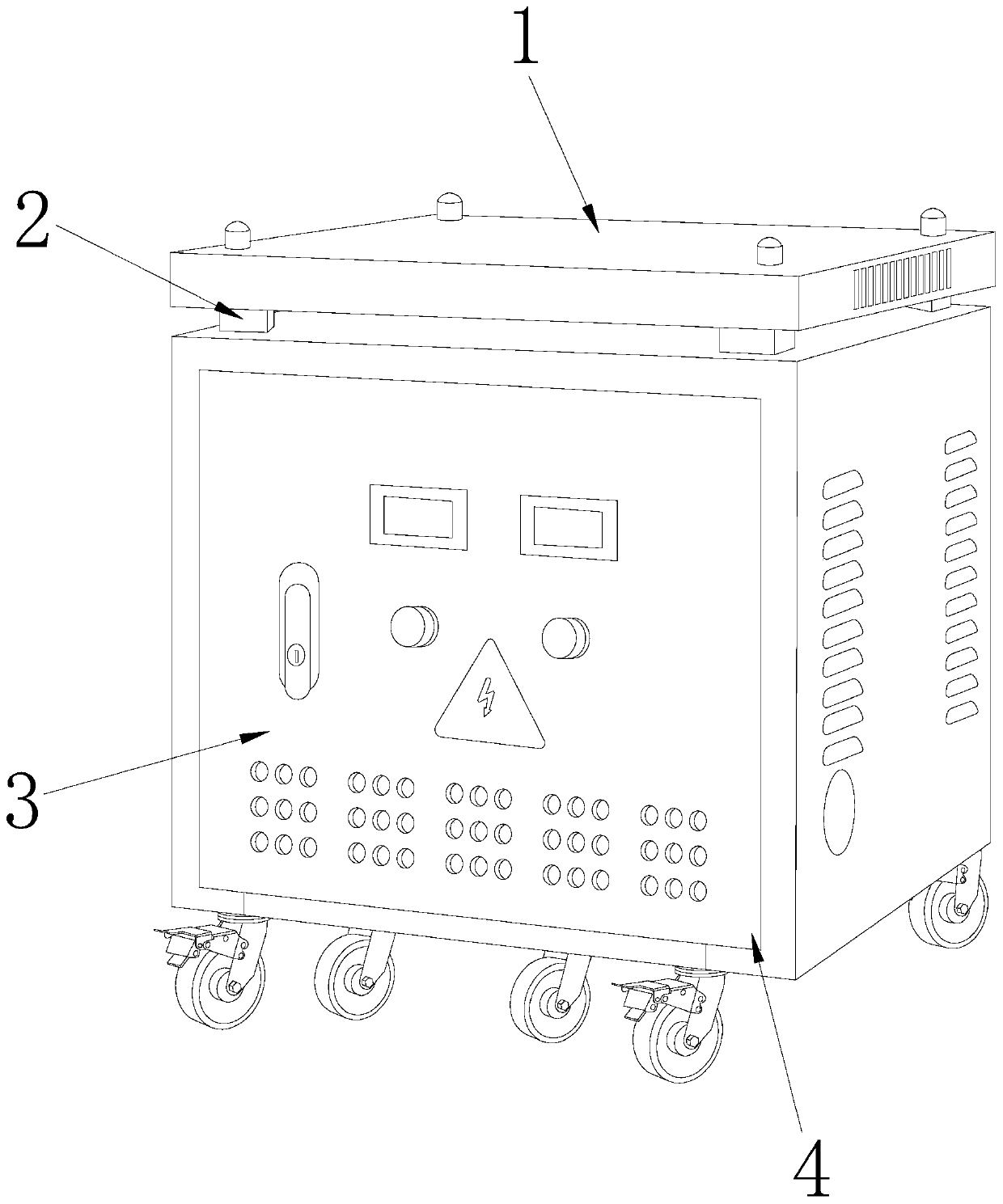
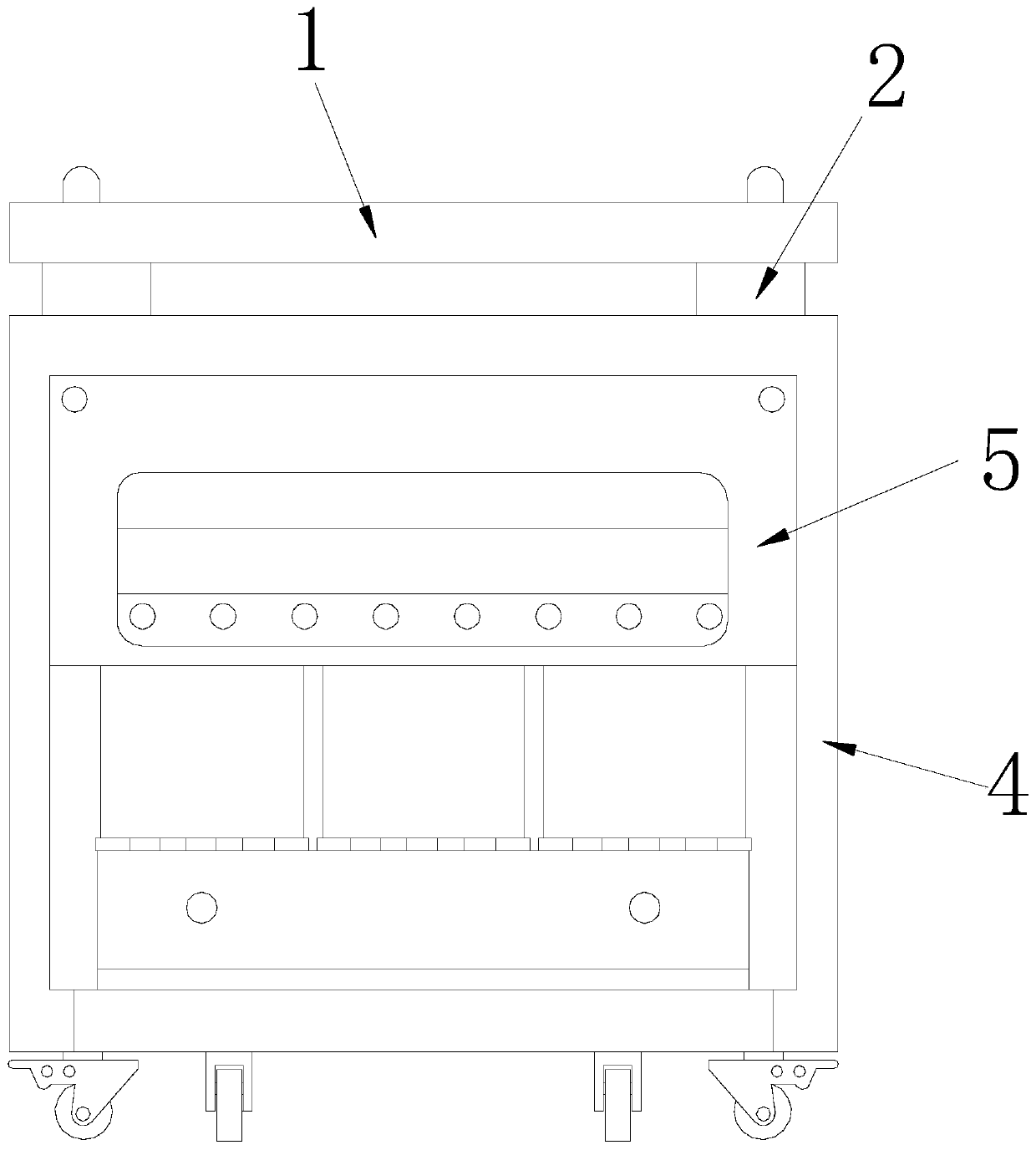
[0032] see figure 1 , the present invention provides a technical solution for a three-phase dry-type isolation transformer: please refer to Figure 1-8 , the present invention provides a technical solution of a three-phase dry-type isolation transformer: its structure includes a top plate 1, a connection block 2, a box door 3, an isolation box 4, and a dry-type transformer 5, and the top four corners of the isolation box 4 Both are connected to the top plate 1 through the connecting block 2, the outer hinge of the isolation box 4 is connected with the box door 3, and the isolation box 4 has a built-in dry-type transformer 5;

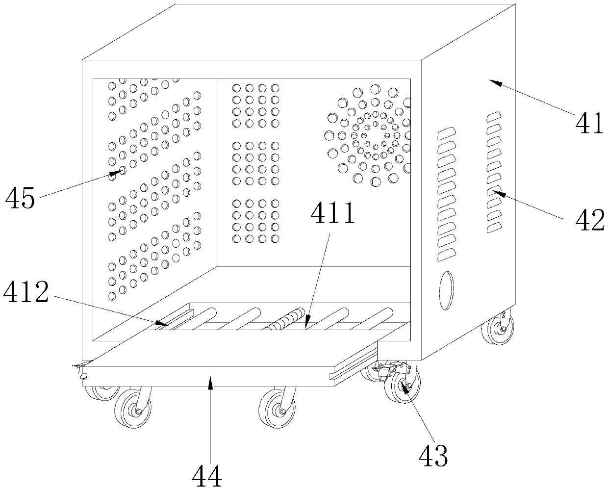
[0033] see Figure 2-3 , the isolation box 4 includes a box body 41, a heat dissipation grill 42, a universal wheel 43, a dry-type transformer placement device 44, and a heat dissipation hole 45. The four corners of the bottom of the box body 41 are mechanically connected with universal wheels. Wheel 43, one side of the box body 41 is evenly distribut...

Embodiment 2

[0039] see Figure 1-8 , the present invention provides a technical solution of a three-phase dry-type isolation transformer: its structure includes a top plate 1, a connection block 2, a box door 3, an isolation box 4, and a dry-type transformer 5, and the top four corners of the isolation box 4 Both are connected to the top plate 1 through the connecting block 2, the outer hinge of the isolation box 4 is connected with the box door 3, and the isolation box 4 has a built-in dry-type transformer 5;

[0040] The isolation box 4 includes a box body 41, a heat dissipation grill 42, universal wheels 43, a dry-type transformer placement device 44, and heat dissipation holes 45. The four corners of the bottom of the box body 41 are mechanically connected with universal wheels. 43. One side of the box body 41 is evenly distributed with heat dissipation holes 45, and the other side is evenly distributed with heat dissipation grilles 42. The bottom of the box body 41 is equipped with a...


PUM


Abstract

The invention discloses a three-phase dry type isolation transformer. The three-phase dry type isolation transformer structurally comprises a top plate, a connecting block, a box door, an isolation box and a dry-type transformer; four corners of the top of the isolation box are connected with the top plate through connecting blocks; a box door is hinged outside the isolation box; and a dry-type transformer is arranged in the isolation box. Compared with the prior art, the three-phase dry type isolation transformer is advantageous in an existing isolation box is modified, a rectangular notch isformed in the isolation box, and then the dry-type transformer placing device is additionally arranged; and a supporting device is additionally arranged at the bottom of the dry-type transformer placing device, so that the novel isolation box is formed, the dry-type transformer can be conveniently installed in the isolation box, the dry-type transformer can be conveniently and horizontally pulledout to be maintained, the dry-type transformer can be prevented from being placed in and taken out of the box to be prevented from rigidly colliding with the box body, the dry-type transformer is well protected, and the service life of the dry-type transformer can be prolonged.

Description

technical field [0001] The invention relates to the technical field of transformers, in particular to a three-phase dry isolation transformer. Background technique [0002] The isolation transformer has the characteristics of small coupling between the output capacitor and the input capacitor, which can more effectively suppress the interference of power grid noise such as lightning, discharge, power grid switching, and motor starting. Therefore, the isolation transformer is more effective in protecting the equipment. Personal safety is the protection of the people who operate the equipment. Since the electromotive force of the isolation transformer is obtained through secondary induction, it will not form a loop with the primary side, so it will not cause electric shock. It can isolate electrical equipment from the grid, and is used in safety occasions or anti-interference occasions. [0003] The transformer is installed in the isolation box. Due to the limited space of th...

Claims


Application Information

Patent Timeline
Patent Type & Authority Applications(China)
IPC IPC(8): H01F27/06H01F27/02
CPCH01F27/002H01F27/02H01F27/025H01F27/06
Inventor 李元飞
Owner 李元飞
Learn More