


Quick Research
Generate reliable direction feasibility study reports for your R&D in just a few steps.

Technical Q&A
Discover and master advanced knowledge NOW. Basics, ideas, possibilities, all at once.

Find Solutions
As an expert in R&D theories, this can generate solutions to your technical problems instantly.

Evaluate Feasibility
Analyze your overall solution with one click, know your potential R&D risks in advance.

Monitor Landscape
Get weekly tech updates, stay abreast of the latest tech innovations and key insights.
Stair three-step bottom die reinforcing device, reinforcing supporting system and construction technology
A reinforcement device and support system technology, applied in the field preparation of formwork/formwork/work frame, construction components, construction, etc., can solve the problem that the rigidity of the formwork cannot meet the construction requirements, the requirements for the stair support system are high, and cleaning is difficult. Large and other problems, to achieve the effect of easy assembly and disassembly, simple structure, and reduced repair costs
- Summary
- Abstract
- Description
- Claims
- Application Information
AI Technical Summary
Problems solved by technology
Method used
Image

Examples
Embodiment 1
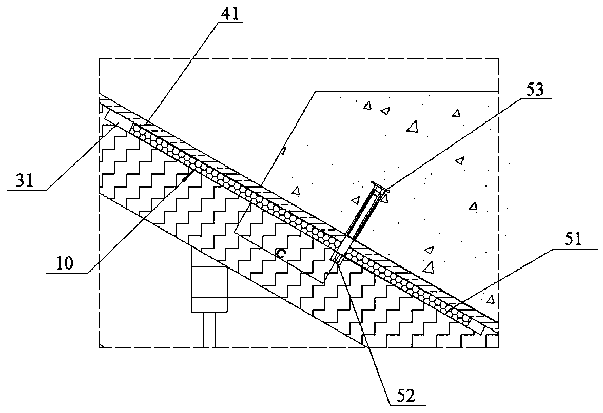
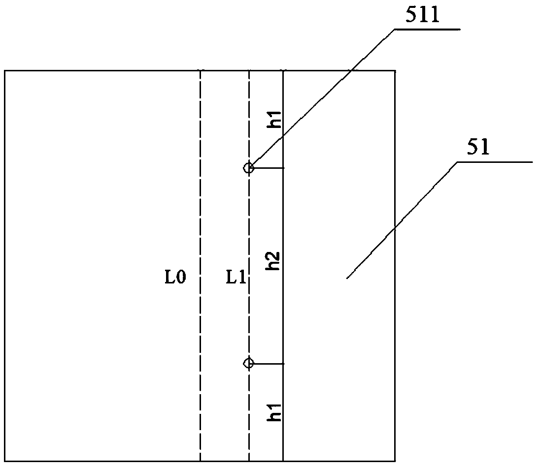
[0036] see Figure 1 to Figure 6 , a three-step bottom form reinforcement device 10 on stairs, including steel plates 51, bolts 52 and nuts 53.
[0037] The steel plate 51 has more than two through holes 511, and the centers of all the through holes 511 are located on the same straight line L1, and the straight line L1 is located on the side of the midline L0 of the steel plate 51. L1 and L0 are represented by dotted lines in the figure. The distance h1 from the center of the through hole 511 at both ends of the straight line L1 to the edge of the steel plate 51 along the direction of the straight line L1 is equal and greater than or equal to 80 mm and less than or equal to 150 mm. The distance h2 between the centers of two adjacent through holes 511 is greater than or equal to 2h1, preferably equal to 2h1. The distance d1 from the center of the through hole 511 to the edge of the steel plate 51 on one side along the direction perpendicular to the straight line L1 is smaller ...
Embodiment 2
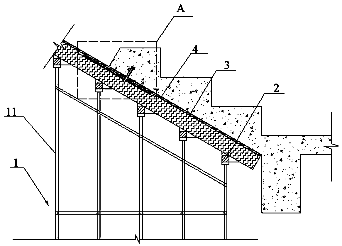
[0044] see figure 1 , a three-step reinforced support system on stairs, including a bottom support 1, a main flute 2 and a secondary flute 3, a bottom form reinforcement device 10 and a stair formwork 4.
[0045] The main flute 2 is parallel to the length direction of the steps of the stairs and is horizontally arranged on the top of the vertical rod 11 of the bottom support 1, and the secondary flute 3 is parallel to the bottom surface of the stairs and supported obliquely on the main flute 2 in a direction perpendicular to the main flute 2. The secondary flute 3 is provided with a groove 31 for accommodating the reinforcing device 10 of the bottom form.
[0046] The structure of the bottom form reinforcement device 10 is the same as that of the three-step bottom form reinforcement device 10 on the stairs in the first embodiment. The steel plate 51 of the bottom form reinforcing device 10 is accommodated in the groove 31 .
[0047] The stair template 4 is supported on the s...
Embodiment 3
[0049] A construction technique for reinforcing a support system in three steps on a staircase, comprising the following steps:
[0050] Install the bottom support 1, install the main flute 2 on the top of the vertical pole 11 of the bottom support 1, install the back flute on the main flute 2 with the side with the groove 31 facing up;
[0051] Place the steel plate 51 in the groove 31 of the back flute, the direction of the straight line L1 formed by the connection of the through holes 511 of the steel plate 51 is placed parallel to the main flute 2, and the short side from the through hole 511 of the steel plate 51 to the edge is placed below That is, the short side from the through hole 511 to the edge of the steel plate 51 perpendicular to the straight line L1 direction is located on the inside of the three steps on the stairs, the long side is located on the outside of the three steps on the stairs, and the through hole 511 is located on the inside of the three steps on t...
PUM
 Abstract
Description
Claims
Application Information
 - R&D Engineer
- R&D Manager
- IP Professional
- Industry Leading Data Capabilities
- Powerful AI technology
- Patent DNA Extraction
Browse by: Latest US Patents, China's latest patents, Technical Efficacy Thesaurus, Application Domain, Technology Topic, Popular Technical Reports.
© 2024 PatSnap. All rights reserved.Legal|Privacy policy|Modern Slavery Act Transparency Statement|Sitemap|About US| Contact US: help@patsnap.com