Urea pyrolysis system and urea pyrolysis method
A urea and pyrolysis technology, which is applied to the urea pyrolysis system and the field of pyrolysis urea, can solve the problems of high operation cost and high power consumption of the system, and achieve the effect of reducing power consumption and operation cost and having a simple structure.
- Summary
- Abstract
- Description
- Claims
- Application Information
AI Technical Summary
Problems solved by technology
Method used
Image

Examples
Embodiment 1
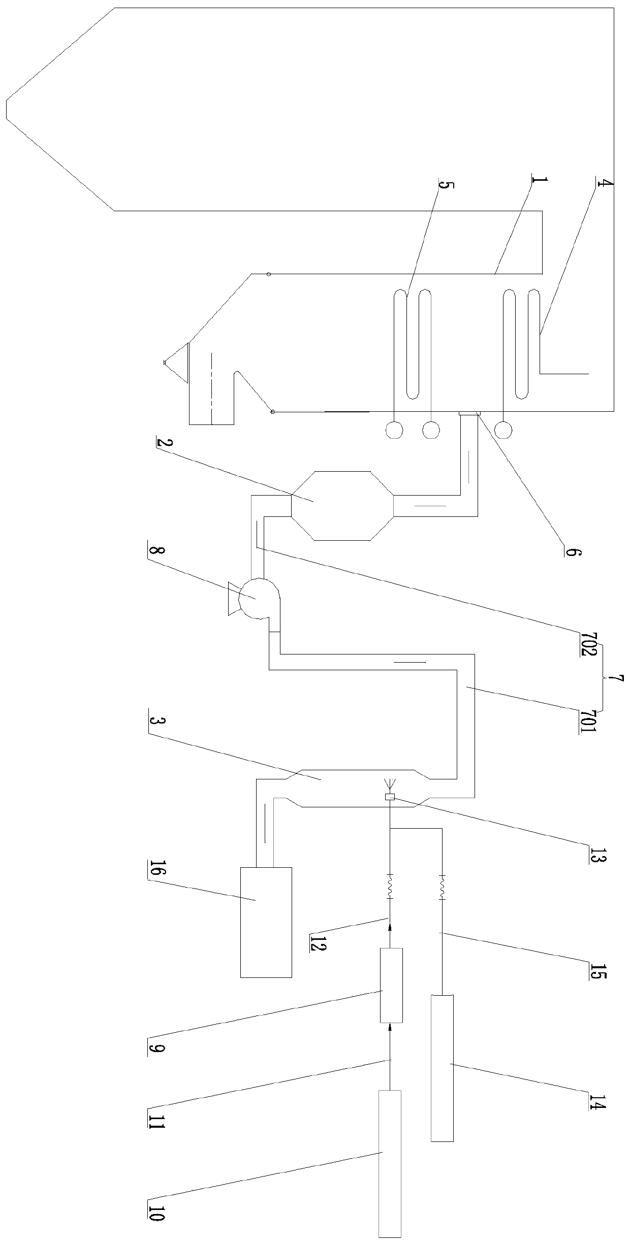
[0023] Embodiment 1 of the present invention: a urea pyrolysis system, comprising a boiler 1, a high-temperature dust removal device 2, and a pyrolysis furnace 3, and the boiler 1 is provided with a low-temperature superheater 4 and a coal-saving coal-saving device arranged below the low-temperature superheater 4 The flue gas outlet 6 is provided at the flue between the low temperature superheater 4 and the economizer 5, the high temperature dust removal device 2 is connected with the flue gas outlet 6, and the high temperature dust removal device 2 passes through the transition flue 7 is connected to the pyrolysis furnace 3 .
Embodiment 2
[0024] Embodiment 2 of the present invention: a urea pyrolysis system, comprising a boiler 1, a high-temperature dust removal device 2, and a pyrolysis furnace 3, and the boiler 1 is provided with a low-temperature superheater 4 and a coal-saving coal-saving device arranged below the low-temperature superheater 4 The flue gas outlet 6 is provided at the flue between the low temperature superheater 4 and the economizer 5, the high temperature dust removal device 2 is connected with the flue gas outlet 6, and the high temperature dust removal device 2 passes through the transition flue 7 is connected to the pyrolysis furnace 3 . The transition flue 7 is provided with a high-temperature induced draft fan 8. The transition flue 7 includes a first transition flue section 701 and a second transition flue section 702. The air inlet of the fan 8 is connected, and the pyrolysis furnace 3 is connected to the air outlet of the high temperature induced draft fan 8 through the second trans...
Embodiment 3
[0025] Embodiment 3 of the present invention: a urea pyrolysis system, comprising a boiler 1, a high-temperature dedusting device 2, and a pyrolysis furnace 3, wherein the boiler 1 is provided with a low-temperature superheater 4 and a coal-saving coal-saving device arranged below the low-temperature superheater 4 The flue gas outlet 6 is provided at the flue between the low temperature superheater 4 and the economizer 5, the high temperature dust removal device 2 is connected with the flue gas outlet 6, and the high temperature dust removal device 2 passes through the transition flue 7 is connected to the pyrolysis furnace 3 . The transition flue 7 is provided with a high-temperature induced draft fan 8. The transition flue 7 includes a first transition flue section 701 and a second transition flue section 702. The air inlet of the fan 8 is connected, and the pyrolysis furnace 3 is connected to the air outlet of the high temperature induced draft fan 8 through the second tran...
PUM
 Abstract
Description
Claims
Application Information
 - R&D
- Intellectual Property
- Life Sciences
- Materials
- Tech Scout
- Unparalleled Data Quality
- Higher Quality Content
- 60% Fewer Hallucinations
Browse by: Latest US Patents, China's latest patents, Technical Efficacy Thesaurus, Application Domain, Technology Topic, Popular Technical Reports.
© 2025 PatSnap. All rights reserved.Legal|Privacy policy|Modern Slavery Act Transparency Statement|Sitemap|About US| Contact US: help@patsnap.com