Bearing series connection device and application method

A technology of tandem device and bearing, used in hand-held tools, manufacturing tools, etc., can solve the problems of bearing dislocation damage, inability to realize bearing series connection, etc., and achieve the effect of high assembly flatness, good assembly quality, and tight integration.

Active Publication Date: 2020-06-23
西峡县飞龙汽车部件有限公司
View PDF6 Cites 2 Cited by
  • Summary
  • Abstract
  • Description
  • Claims
  • Application Information

AI Technical Summary

Problems solved by technology

When press-fitting the bearing on the rotor, put the rotor body into the concave cavity first, ensure that the lower shaft of the rotor is located in the through hole 1, put the bearing into the accommodation cavity, temporarily fix it through the fixing structure, press down the lower mold, and the rotor The upper shaft passes through the bearing and the second through hole in order to achieve the purpose of inserting the bearing into the upper shaft of the rotor. Since the upper shaft of the rotor and the bearing are an interference fit, the friction between the two is greater than the friction between the bearing and the fixed structure After the pressing is completed, the upper mold rises, and the bearing breaks away from the fixed structure. This device has high pressing accuracy and good pressing effect, but there is no locking component to fix the outer ring on the assembled bearing, and the pressing is connected in series with the bearing. When the bearing is used, the upper bearing outer ring impacts the lowermost bearing outer ring, causing dislocation damage to the lowermost bearing, and it is impossible to realize the series connection of two or more bearings

Method used


Image

  • Bearing series connection device and application method
  • Bearing series connection device and application method
  • Bearing series connection device and application method

Examples


Embodiment Construction

[0048] The technical solutions in the embodiments of the present invention will be clearly and completely described below in conjunction with the drawings in the embodiments of the present invention. Obviously, the described embodiments are only a part of the embodiments of the present invention, rather than all the embodiments. Based on the embodiments of the present invention, all other embodiments obtained by those of ordinary skill in the art without creative work shall fall within the protection scope of the present invention.

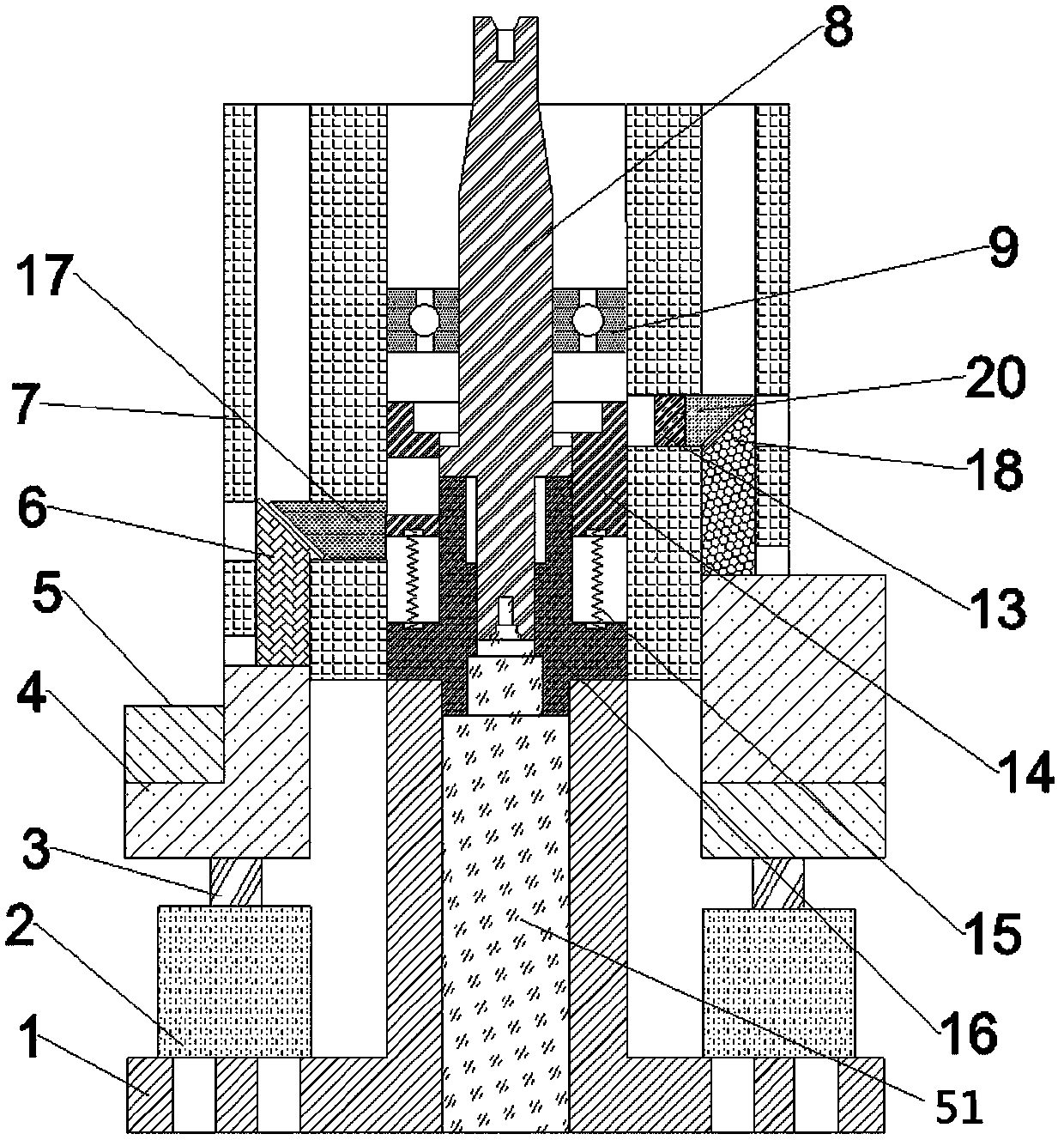
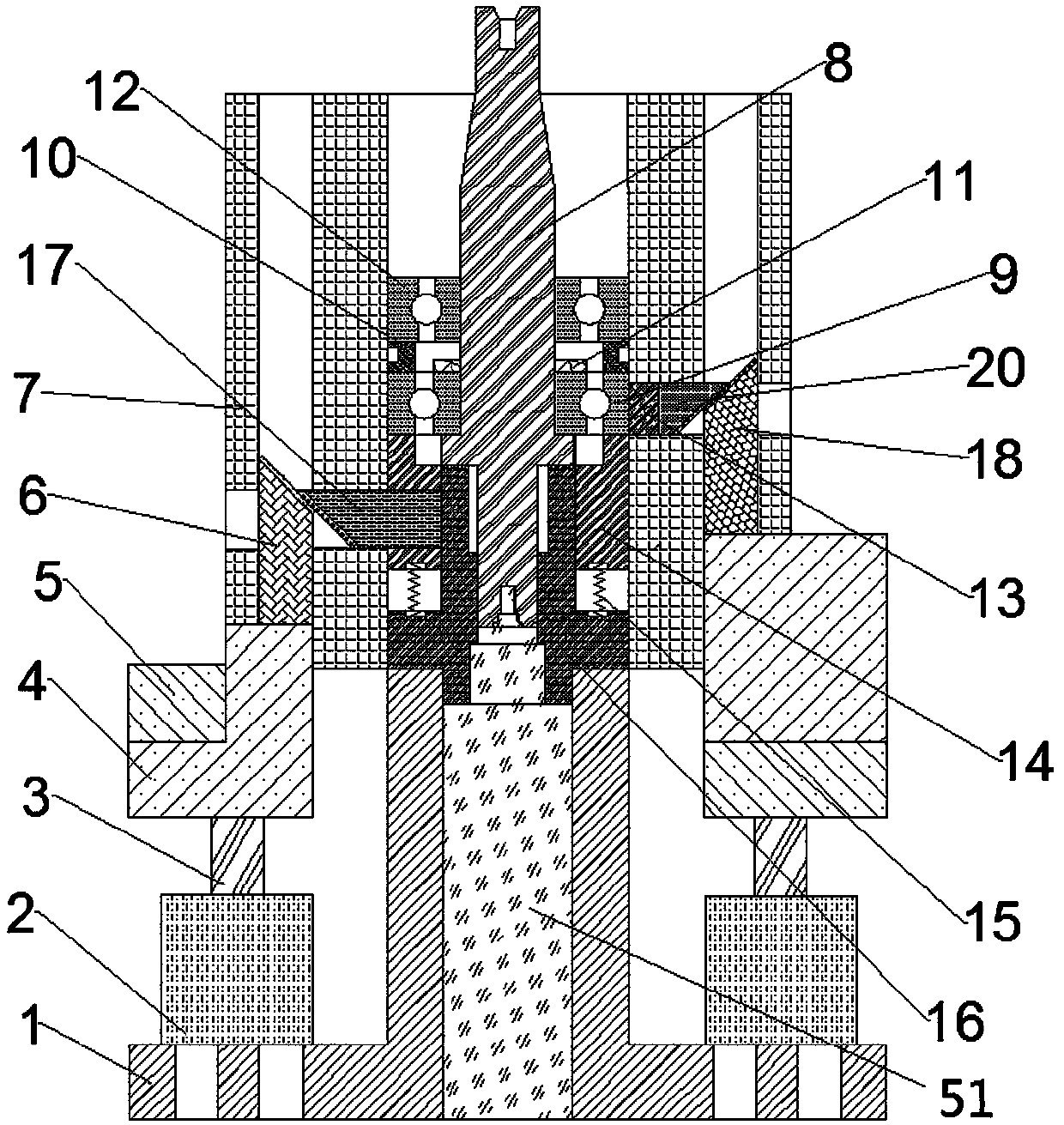
[0049] A bearing tandem device includes a base 1, and the structure of the base 1 is as Figure 4 As shown, the base 1 is provided with a bottom hole 22, a cylinder accommodating cavity 23, a fixture wire hole 25 and a mandrel mounting hole 26, of which six cylinder accommodating cavities 23 are arranged in a circumferential shape. A mandrel 16 is provided on the base 1, and the structure of the mandrel 16 is as Figure 5 As shown, the bottom end of ...


PUM


Abstract

The invention discloses a bearing series connection device and an application method. The bearing series connection device comprises a base; a mandrel mounting hole is arranged on the base; a mandrelis arranged on the base; the bottom end of the mandrel is inserted into the mandrel mounting hole; a pump shaft fit cavity matched with a pump shaft is arranged in the mandrel; a first shoulder is arranged on the periphery of the lower part of the mandrel; the lower end surface of the first shoulder is attached to the upper end surface of the base; a cushion block is arranged above the first shoulder; the cushion block is arranged on the mandrel above the first shoulder in a sleeving mode; a spring is arranged between the cushion block and the first shoulder; a clamp is arranged outside the cushion block in a sleeving mode and fixed on the base; a locking mechanism for fixing an outer ring of a lowermost bearing is arranged among the base, the clamp and the cushion block; a first bearing is firstly assembled, and the outer ring of the first bearing is fixed and then connected with other bearings in series; the use is simple; when the bearings are connected in series, the outer ring ofthe lowermost bearing is not staggered; and the serial assembly of two or more bearings is realized, and the assembly quality is good.

Description

Technical field [0001] The invention designs the field of bearing assembly, and in particular relates to a bearing series device and a use method. Background technique [0002] Under normal circumstances, when a bearing needs to be installed on the pump shaft, the worker needs to manually put one bearing into the lower press fitting mold, put the pump shaft into the press, put the other bearing into the upper end of the pump shaft, and hold it by hand. The pump shaft is press-fitted with bearings at both ends. This type of press-fitting device has a high scrap rate, low one-time pass rate, poor coaxiality after connection, low press-fitting process efficiency, and high operating risk factor. [0003] The prior art discloses a bearing pressing device, which includes a base, a lower mold set on the base, and an upper mold set above the lower mold. The lower mold has a vertical cavity for accommodating the rotor body. The cavity is coaxially arranged with a through hole for accommoda...

Claims


Application Information

Patent Timeline
IPC IPC(8): B25B27/06
CPCB25B27/06
Inventor 冯长虹朱勇江慧丽袁源袁小凡靳三甲李晓娜
Owner 西峡县飞龙汽车部件有限公司
Why Eureka
Try Eureka