
Suspension mechanism, lifting and lowering device and vehicle

A technology of suspension mechanism and lifting device, applied in the direction of motor vehicles, vehicle springs, vehicle parts, etc., can solve the problems of unbalanced force, unable to achieve self-locking, heavy weight, etc., and achieve the effect of large adjustment range

Inactive Publication Date: 2020-06-19
SZ DJI TECH CO LTD
View PDF6 Cites 4 Cited by
  • Summary
  • Abstract
  • Description
  • Claims
  • Application Information

AI Technical Summary

Problems solved by technology

However, due to the heavy weight of the pan / tilt, camera and other equipment installed on the chassis, this method of driving the chassis to move up and down by rotation cannot achieve self-locking, and sometimes the force will be unbalanced

Method used


Image

  • Suspension mechanism, lifting and lowering device and vehicle
  • Suspension mechanism, lifting and lowering device and vehicle
  • Suspension mechanism, lifting and lowering device and vehicle

Examples


Embodiment Construction

[0026] Some embodiments of the present invention will be described in detail below in conjunction with the accompanying drawings. In the case of no conflict, the following embodiments and features in the embodiments can be combined with each other.

[0027] In the description of the present invention, it should be understood that the orientations or positional relationships indicated by the terms "upper", "lower", "top", "bottom", "inner" and "outer" are based on those shown in the accompanying drawings. Orientation or positional relationship is only for the convenience of describing the present invention and simplifying the description, and does not indicate or imply that the referred device or element must have a specific orientation, be constructed and operated in a specific orientation, and thus should not be construed as a limitation of the present invention.

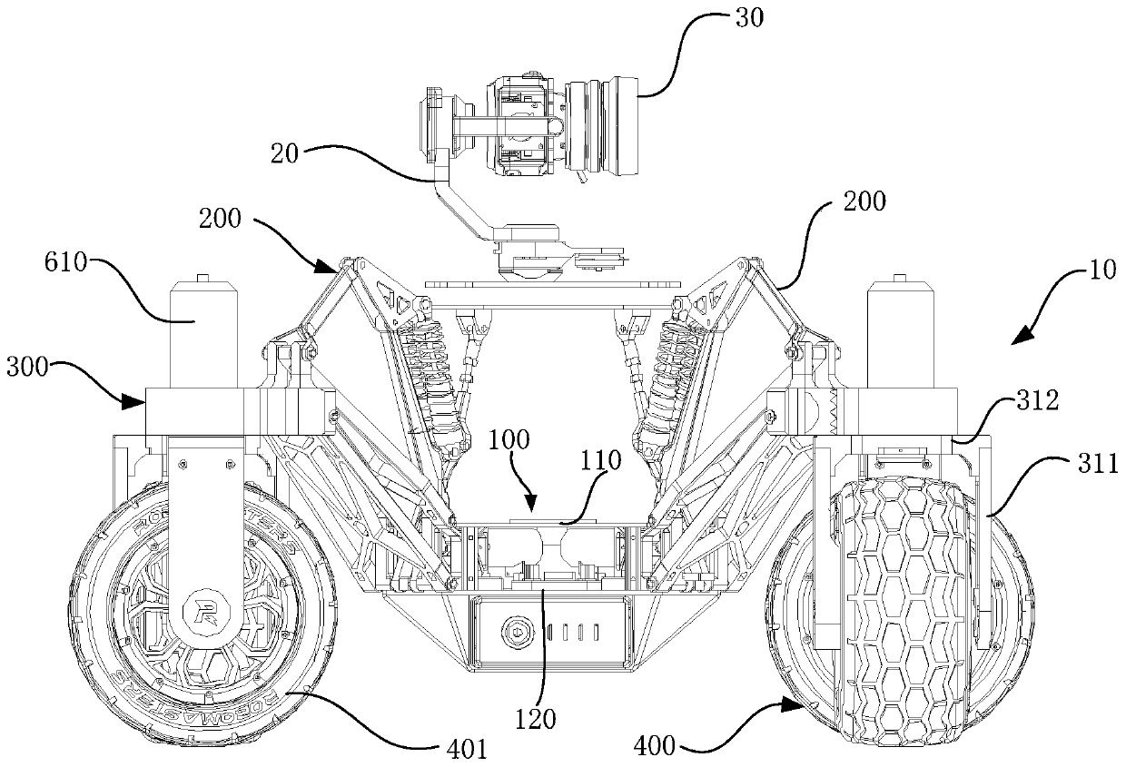
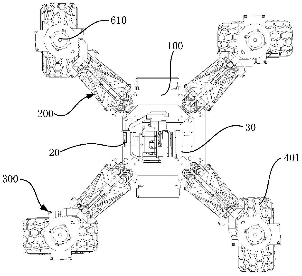
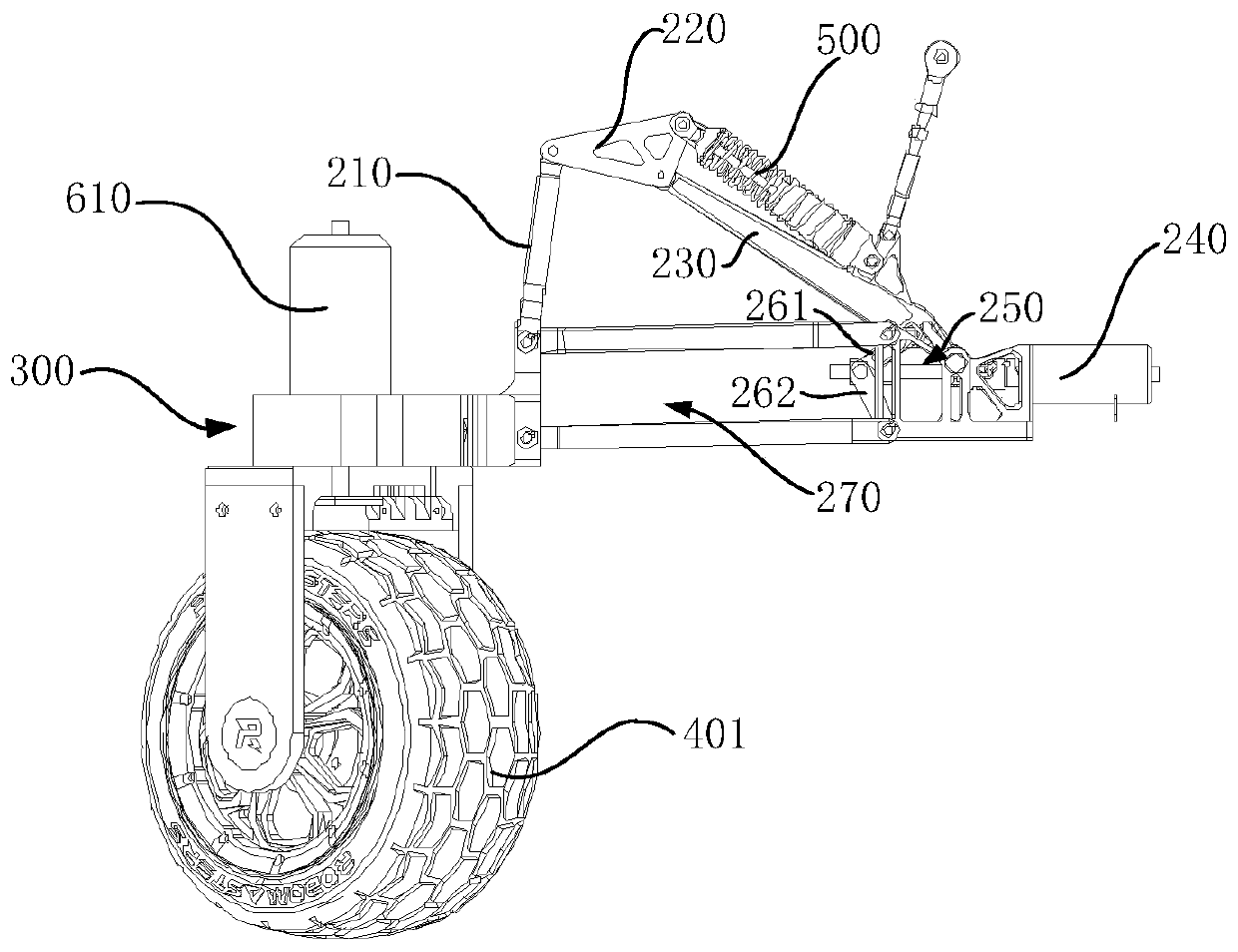
[0028] figure 1 It is a schematic diagram of the first deformation mode of the vehicle 10 provided in this embo...


PUM


Abstract

A suspension mechanism (300), configured to connect wheel sets (400) and a chassis (100) of a vehicle and comprising: a first part (330) and a second part (340). One of the first part (330) and the second part (340) is connected to the chassis (100), and the other one of the first part (330) and the second part (340) is rotationally connected to the axles of the wheel sets (400). At least one of the first part (330) and the second part (340) can rotate with respect to a rotation axis to drive the chassis (100) to move up and down, wherein the rotation axis is parallel to the central axis of the axles. By providing the suspension mechanism for connecting the chassis and the wheel sets, the chassis can be lifted and lowered by relatively rotating the first part and the second part of the suspension mechanism so as to adjust the center of gravity of the vehicle, so that the vehicle can change the height of the chassis according to actual needs in high-speed movement, low-speed movement, slop climbing, or other scenarios. Also disclosed are a lifting and lowering device and a vehicle.

Description

technical field [0001] The invention relates to a suspension mechanism, a lifting device and a vehicle, and belongs to the technical field of image shooting auxiliary equipment. Background technique [0002] In the shooting of the film industry or photography enthusiasts, a gimbal car equipped with a gimbal and a camera will be used for remote shooting and first-person driving to shoot pictures with special perspectives. Existing pan-tilt vehicles generally connect the chassis and the axles of the wheelset together, so that the chassis can be driven up and down by driving the wheel set to rotate to adjust the overall center of gravity of the pan-tilt vehicle to reduce the possibility of the pan-tilt vehicle tipping over . However, due to the heavy weight of the pan / tilt, camera and other equipment installed on the chassis, this method of driving the chassis to move up and down by rotation cannot achieve self-locking, and sometimes the force will be unbalanced. Contents of...

Claims


Application Information

Patent Timeline
Patent Type & Authority Applications(China)
IPC IPC(8): B60G17/015B60G3/20
CPCB60G17/015B60G3/20B60G2200/422B60G2202/42B60G2500/30B62D63/04B60G17/00B60G17/005B62D63/02
Inventor 包玉奇任冠男刘玉洪
Owner SZ DJI TECH CO LTD
Learn More