
Excitation type demand response implementation method considering dynamic response process quality

A demand response and dynamic response technology, applied in data processing applications, instruments, computing, etc., can solve problems such as the difficulty of aggregating resources on the user side, dampening user enthusiasm, and unfavorable long-term development of incentive-based demand response, achieving the effect of improving the implementation level

Active Publication Date: 2020-06-19
JIANGSU ELECTRIC POWER CO +1
View PDF1 Cites 2 Cited by
  • Summary
  • Abstract
  • Description
  • Claims
  • Application Information

AI Technical Summary

Problems solved by technology

[0003] In the actual application process, the settlement of incentive-based demand response is particularly important. A settlement plan that is too strict may discourage the enthusiasm of users, while a settlement plan that is too loose is not conducive to the long-term development of incentive-based demand response.
Undoubtedly, the incentive-based demand response settlement should be linked to the response effect. The existing literature mainly considers the difference between the target load and the actual load, that is, whether the demand response target is met as a whole, and lacks the reliability, volatility and Dynamic response process indicators including deviation degree, which makes it difficult for user-side aggregated resources to participate in power grid dispatching like conventional units

Method used


Image

  • Excitation type demand response implementation method considering dynamic response process quality
  • Excitation type demand response implementation method considering dynamic response process quality
  • Excitation type demand response implementation method considering dynamic response process quality

Examples


Embodiment 1

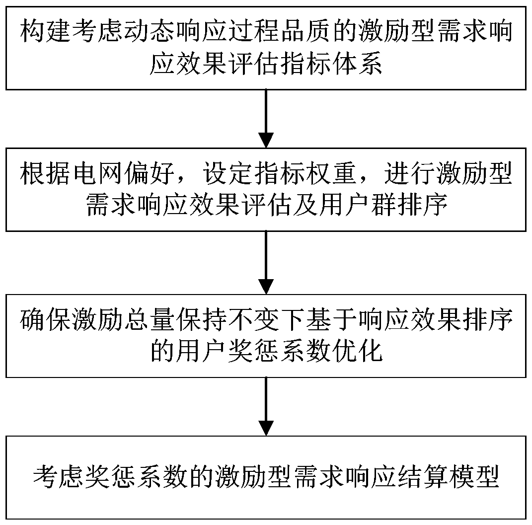
[0059] Embodiment one: as attached figure 1 As shown, an implementation method of incentive demand response considering the quality of dynamic response process includes the following steps:

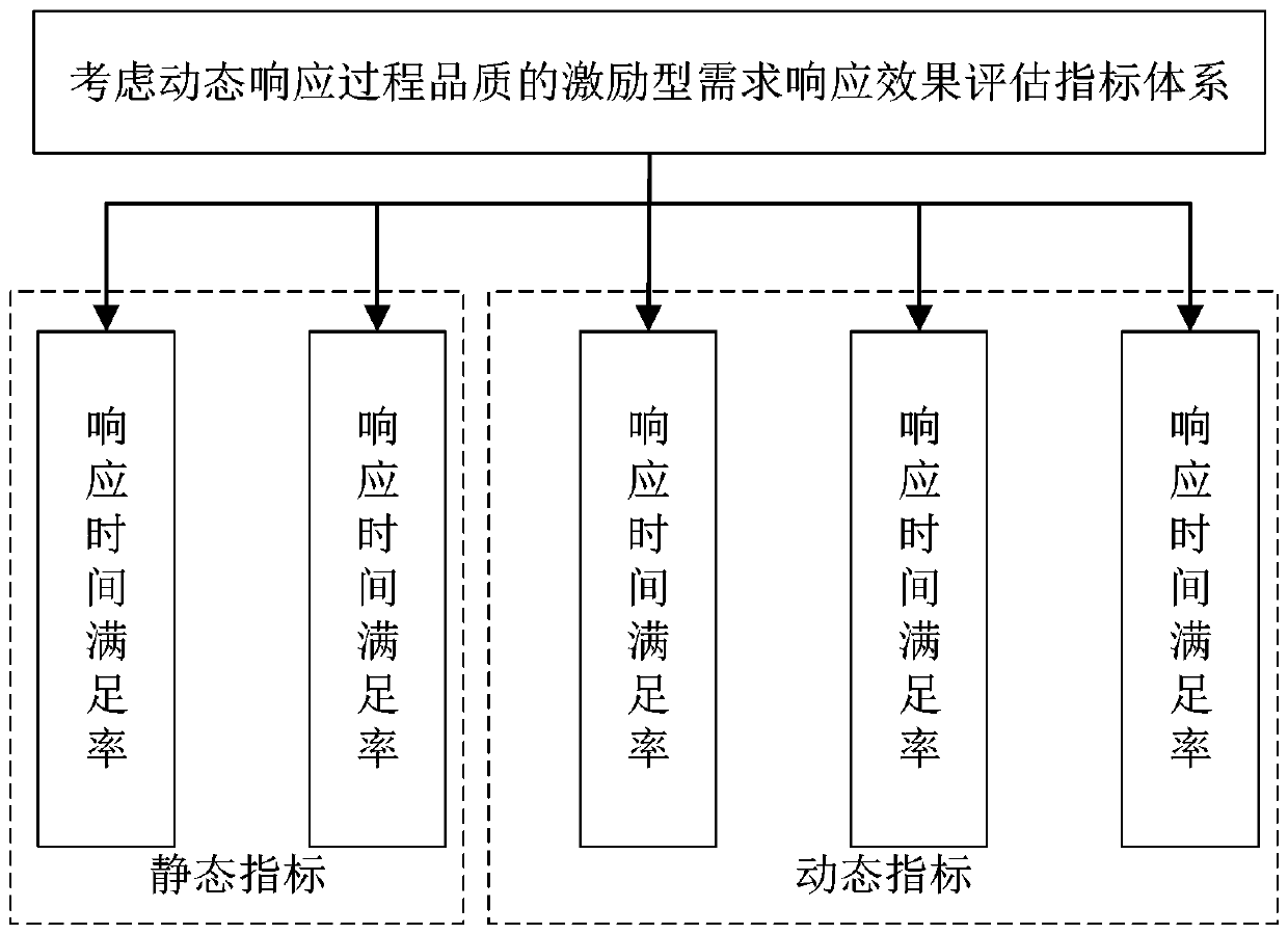
[0060] Step 1: Construct an incentive demand response evaluation index system that considers the quality of the dynamic response process;

[0061] Step 2: Use the incentive demand response effect evaluation index system to evaluate the grid users to obtain the evaluation results of each grid user, and sort the grid users according to the evaluation results;

[0062] Step 3: Under the condition of ensuring that the total amount of incentives remains unchanged, determine the corresponding reward and punishment coefficients for grid users based on the ranking of grid users;

[0063] Step 4: Based on the reward and punishment coefficients corresponding to grid users and the expected incentive fees of each grid user, the actual incentive fees corresponding to each grid user are obtained, and ...


PUM


Abstract

The invention relates to an excitation type demand response implementation method considering the ynamic response process quality. The method comprises the following steps: 1, constructing an excitation type demand response effect evaluation index system considering the quality of the dynamic response process; 2, evaluating the power grid users by utilizing the excitation type demand response effect evaluation index system to obtain evaluation results of the power grid users, and sorting the power grid users according to the evaluation results; 3, determining rewards and punishment coefficients corresponding to the power grid users on the basis of the sorting of the power grid users under the condition of ensuring that the total excitation amount remains unchanged; 4, based on the reward and punishment coefficients corresponding to the power grid users and the expected incentive expenses of the power grid users, obtaining actual incentive expenses corresponding to the power grid users,wherein the actual incentive expenses corresponding to the power grid users form an incentive demand response scheme; and 5, implementing an excitation type demand response scheme. According to the invention, the implementation level of excitation type demand response can be improved, and an electric power company is helped to better aggregate user side resources to participate in power grid operation.

Description

technical field [0001] The invention belongs to the field of power demand side management and control, and in particular relates to an implementation method of an incentive demand response considering the quality of a dynamic response process. Background technique [0002] Under the dual pressure of continuously widening peak-to-valley difference on the grid side and efficient utilization of comprehensive energy, constructing virtual power plants through various demand response measures to participate in grid operation has become a current research hotspot and practice focus. For more than ten years, incentive-based demand response has developed rapidly in my country, especially in high-load areas, and a complete set of demand response implementation system from "theoretical model-technical standards-engineering application" has been formed. Significant applications have been achieved in aspects such as fast response to large users. [0003] In the actual application process...

Claims


Application Information

Patent Timeline
IPC IPC(8): G06Q10/06G06Q50/06
CPCG06Q10/06315G06Q50/06
Inventor 汤峻周飞丁敏董晓峰李石顾韧杨晨吕东刘博葛卫梁杨文王辉
Owner JIANGSU ELECTRIC POWER CO
Learn More