Mutual calibration method based on alternating electromagnetic field positioning and inertial sensor

An inertial sensor and alternating electromagnetic field technology, applied in the field of human motion capture, can solve problems such as skin pulling, rotation measurement accuracy drop, and fear of light interference, etc., to prolong the use time, eliminate metal interference, and compensate for inaccurate measurement accuracy.

Pending Publication Date: 2020-06-19
CHENGDU SIWUGE TECH CO LTD
View PDF1 Cites 0 Cited by
  • Summary
  • Abstract
  • Description
  • Claims
  • Application Information

AI Technical Summary

Problems solved by technology

[0003] The first is motion capture, such as camera motion capture technology, which has the disadvantages of being afraid of light interference and occlusion;
[0004] The second type is the inertial motion capture device, such as the anti-metal interference inertial motion capture, there is a problem that the accuracy drifts with time and cannot be used for a long time;
[0005] The third type is external electromagnetic field capture, such as electromagnetic capture devices, which must be used within the range of the external antenna system and are very susceptible to interference;
[0006] The fourth type is wearable electromagnetic field capture, such as the electromagnetic capture technology based on human body wear, such as patent CN201711258283.X, there is a problem that the accuracy of small-scale rotation measurement is reduced due to the influence of skin artifacts and other factors; in this patent Since the action is calculated by measuring the relative distance and angle change between markers, since the human skin is an elastic surface, when the bone moves, the position of the marker is also pulled by the skin and muscles, so the distance and angle of the marker The change is the superposition of skin and bone movement. When the scale of bone movement is relatively small, the impact of skin pulling will become larger, and this effect often makes the test deviate.

Method used


Image

  • Mutual calibration method based on alternating electromagnetic field positioning and inertial sensor
  • Mutual calibration method based on alternating electromagnetic field positioning and inertial sensor

Examples


Embodiment Construction

[0037] In order to understand the above-mentioned purpose, features and advantages of the present invention more clearly, the present invention will be further described in detail below in conjunction with the accompanying drawings and specific embodiments. It should be noted that, under the condition of not conflicting with each other, the embodiments of the present application and the features in the embodiments can be combined with each other.

[0038] In the following description, many specific details are set forth in order to fully understand the present invention. However, the present invention can also be implemented in other ways different from the scope of this description. Therefore, the protection scope of the present invention is not limited by the following disclosure. limitations of specific examples.

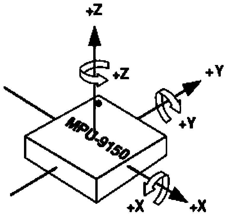
[0039] First, based on the principle of measuring motion with a 9-axis sensor, the process of measuring motion information with a commercial 9-axis sensor is as ...


PUM


Abstract

The invention discloses a mutual calibration method based on alternating electromagnetic field positioning and an inertial sensor. The method comprises the steps: enabling one type of electromagneticfield radiator in a human body posture obtaining system to correspond to the inertial sensor, and enabling the type of electromagnetic field radiator and the inertial sensor to obtain the displacementinformation of a target at the same time; obtaining angle information of the electromagnetic field radiator relative to another electromagnetic field radiator based on a human body posture obtainingsystem; calibrating the angle information, obtained by the inertial sensor, in the horizontal direction of the target by utilizing the angle information; an inertial motion capture device is combinedwith an alternating electromagnetic field position calculation system; an alternating electromagnetic field position calculation system and inertia six-axis sensor angle calculation are used for mutual calibration, and the geomagnetic meter is replaced with angle information in one direction calculated by the alternating electromagnetic field position calculation system and the inertia six-axis sensor angle calculation, so that the inertia six-axis sensor obtains a long-term stable calibration basis, and respective problems are solved.

Description

technical field [0001] The invention relates to the field of human body motion capture, in particular to a method for mutual calibration of positioning and inertial sensors based on alternating electromagnetic fields. Background technique [0002] The current human motion capture technologies mainly include: [0003] The first is motion capture, such as camera motion capture technology, which has the disadvantages of being afraid of light interference and occlusion; [0004] The second type is the inertial motion capture device, such as the anti-metal interference inertial motion capture, there is a problem that the accuracy drifts with time and cannot be used for a long time; [0005] The third type is external electromagnetic field capture, such as electromagnetic capture devices, which must be used within the range of the external antenna system and are very susceptible to interference; [0006] The fourth type is wearable electromagnetic field capture, such as the elec...

Claims


Application Information

Patent Timeline
Patent Type & Authority Applications(China)
IPC IPC(8): G01C25/00
CPCG01C25/00G01C25/005
Inventor 周密胡骁
Owner CHENGDU SIWUGE TECH CO LTD
Why Eureka
Try Eureka