Battery replacement control method and system, electronic equipment and storage medium
A technology for battery swapping equipment and power control, which is applied in charging stations, electric vehicles, vehicle energy storage, etc., and can solve the problems of long battery swapping time and low efficiency
- Summary
- Abstract
- Description
- Claims
- Application Information
AI Technical Summary
Problems solved by technology
Method used
Image
Examples
Embodiment 1
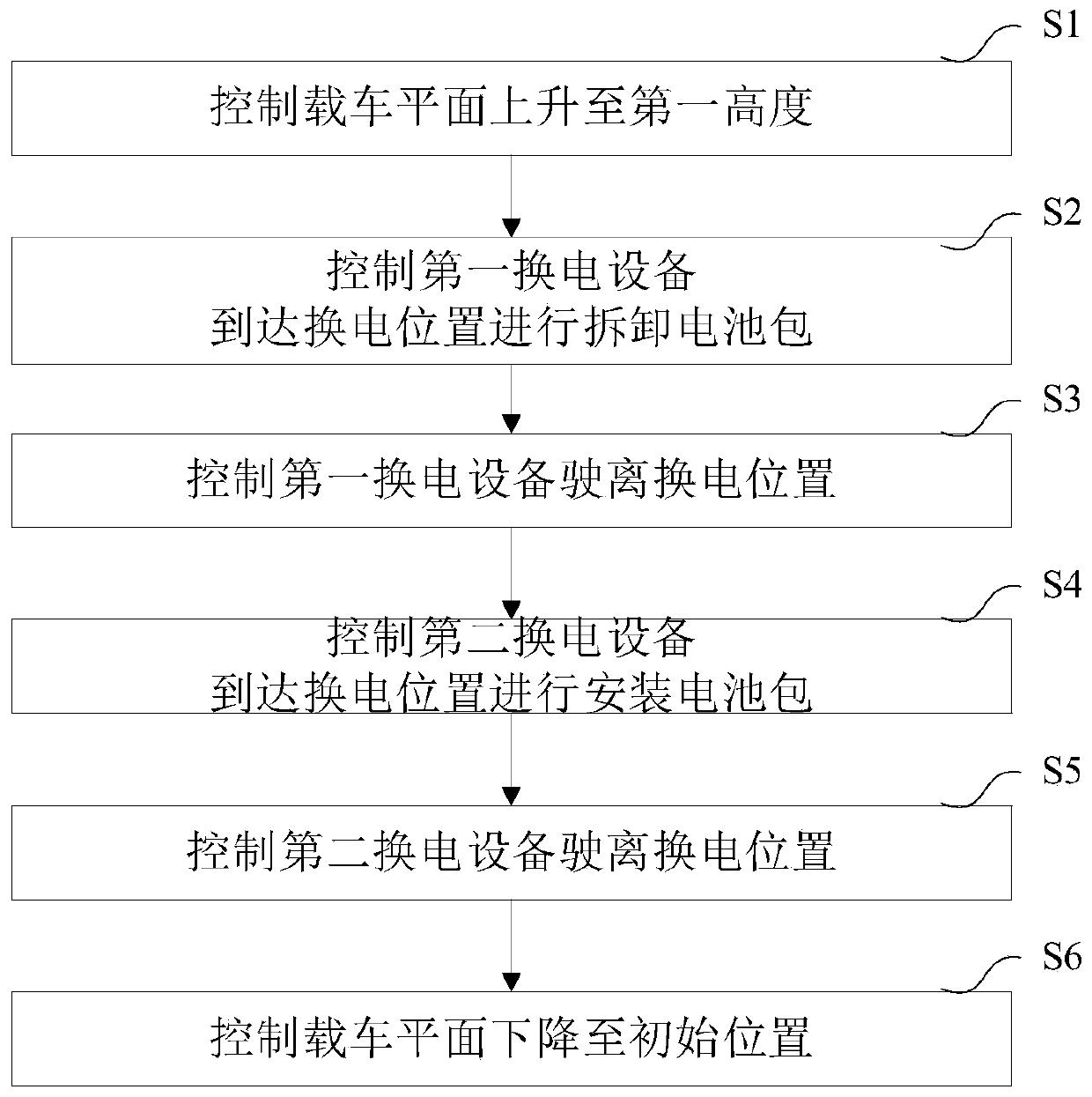
[0144] This embodiment provides a battery replacement control method, figure 2 shows the flowchart of this embodiment, refer to figure 2 , the battery replacement control method in this embodiment includes:
[0145] S1: Control the vehicle loading plane to reach the first height;
[0146] S2: Control the first power swapping device to reach the power swapping position to disassemble the battery pack;
[0147] S3: Control the first battery swapping device to move away from the battery swapping position;
[0148] S4: Control the second power swapping device to arrive at the power swapping position to install the battery pack;
[0149] S5: Control the second battery swapping device to move away from the battery swapping position;
[0150] S6: Control the vehicle loading plane to return to the initial position.
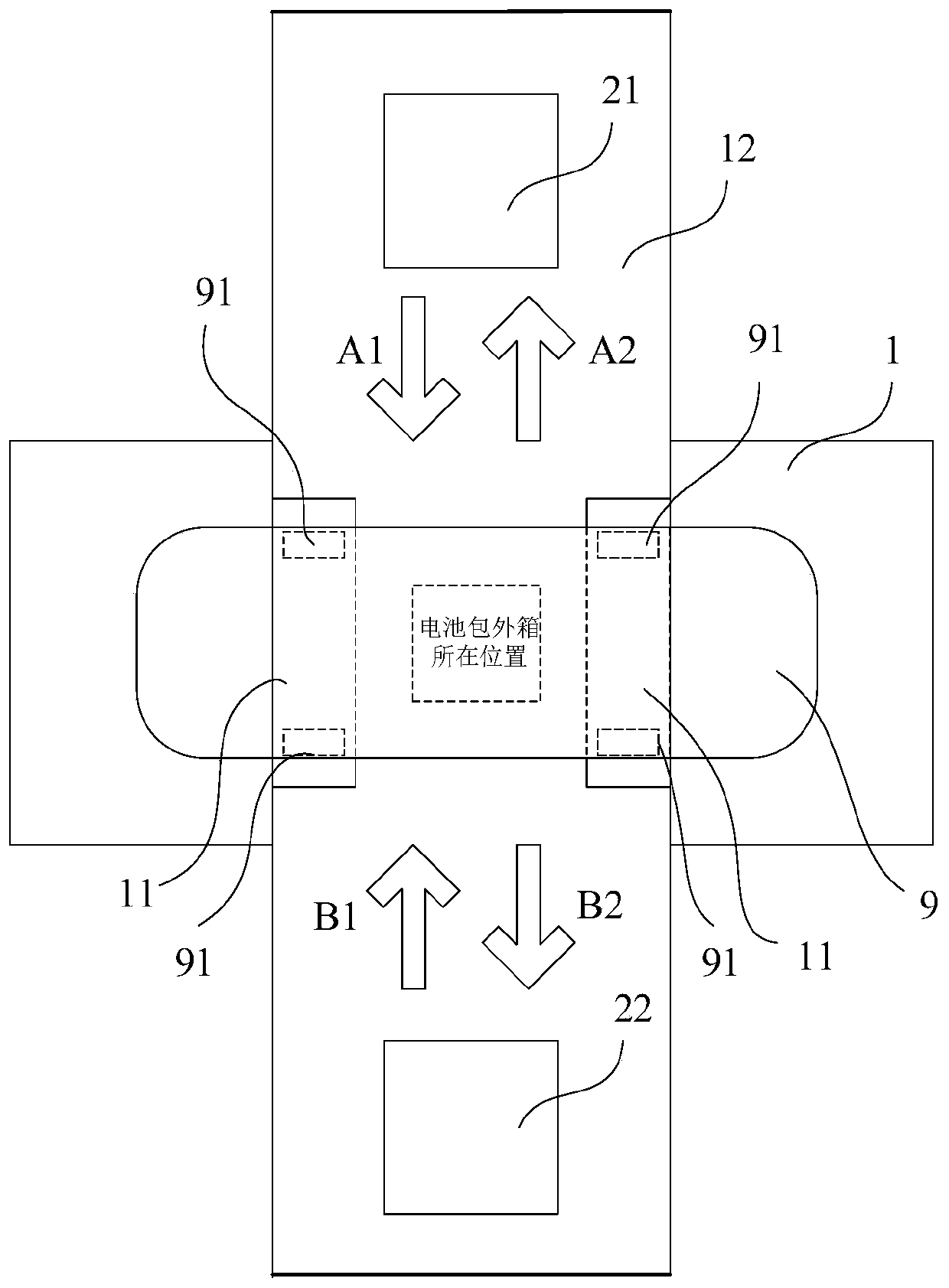
[0151] Among them, such as image 3 As shown, the initial height h0 is the height of the vehicle-carrying plane 11 when it is not raised and lowered. When the veh...
Embodiment 2
[0189] This embodiment provides a battery replacement control system, which controls the clamping lane, the first battery replacement equipment, and the second battery replacement equipment. Figure 16 shows the module diagram of this embodiment, refer to Figure 16 , the power exchange control system of this embodiment includes:
[0190] The clamping lane control module 41 is used to control the vehicle-carrying plane to reach the first height;
[0191] The battery removal control module 42 is used to control the first power exchange device to arrive at the power exchange position to remove the battery pack, and to control the first power exchange device to leave the power exchange position;
[0192] A battery control module 43 is installed, which is used to control the second power exchange device to arrive at the power exchange position to install the battery pack, and control the second power exchange device to leave the power exchange position;
[0193] In this embodime...
Embodiment 3
[0233] Figure 17 It is a schematic structural diagram of an electronic device provided by Embodiment 3 of the present invention. The electronic device includes a memory, a processor, and a computer program stored in the memory and operable on the processor, and the processor implements a method of Embodiment 1 when executing the program. Figure 17 The electronic device 50 shown is only an example, and should not limit the functions and scope of use of the embodiments of the present invention.
[0234] Such as Figure 17 As shown, electronic device 50 may take the form of a general-purpose computing device, which may be a server device, for example. Components of the electronic device 50 may include, but are not limited to: at least one processor 51 , at least one memory 52 , and a bus 53 connecting different system components (including the memory 52 and the processor 51 ).
[0235] The bus 53 includes a data bus, an address bus and a control bus.
[0236] The memory 52 ...
PUM
 Abstract
Description
Claims
Application Information
 - R&D
- Intellectual Property
- Life Sciences
- Materials
- Tech Scout
- Unparalleled Data Quality
- Higher Quality Content
- 60% Fewer Hallucinations
Browse by: Latest US Patents, China's latest patents, Technical Efficacy Thesaurus, Application Domain, Technology Topic, Popular Technical Reports.
© 2025 PatSnap. All rights reserved.Legal|Privacy policy|Modern Slavery Act Transparency Statement|Sitemap|About US| Contact US: help@patsnap.com


