
Cloth cutting machine for garment processing

A cutting machine and fabric technology, applied in the field of garment processing, can solve problems such as wasting time and tediousness

Active Publication Date: 2021-03-09
吴江桑尚丝绸有限公司
View PDF4 Cites 0 Cited by
  • Summary
  • Abstract
  • Description
  • Claims
  • Application Information

AI Technical Summary

Problems solved by technology

[0002] In the flat cutting process of clothing, the cutter usually places the fabric on a flat table, and cuts after drawing the cutting marks. In the actual cutting process, the cutter needs to choose different sizes according to the parts and sizes of the clothing to be made. different fabrics or cut and switch between different fabrics according to actual needs, while the existing cutting table can only perform simple cutting work, the fabric roller and the cutting table are placed separately, if you need different sizes of fabrics or different kinds of fabrics For the conversion, it is necessary to take out the required fabric roller, measure and cut it. In the fabric cutting that needs to frequently cut different sizes and different fabrics, it is cumbersome and time-consuming to manually take and place the fabric roller to take the cloth and cut it.

Method used


Image

  • Cloth cutting machine for garment processing
  • Cloth cutting machine for garment processing
  • Cloth cutting machine for garment processing

Examples


specific Embodiment approach 1

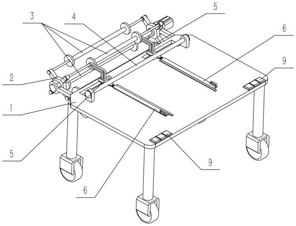
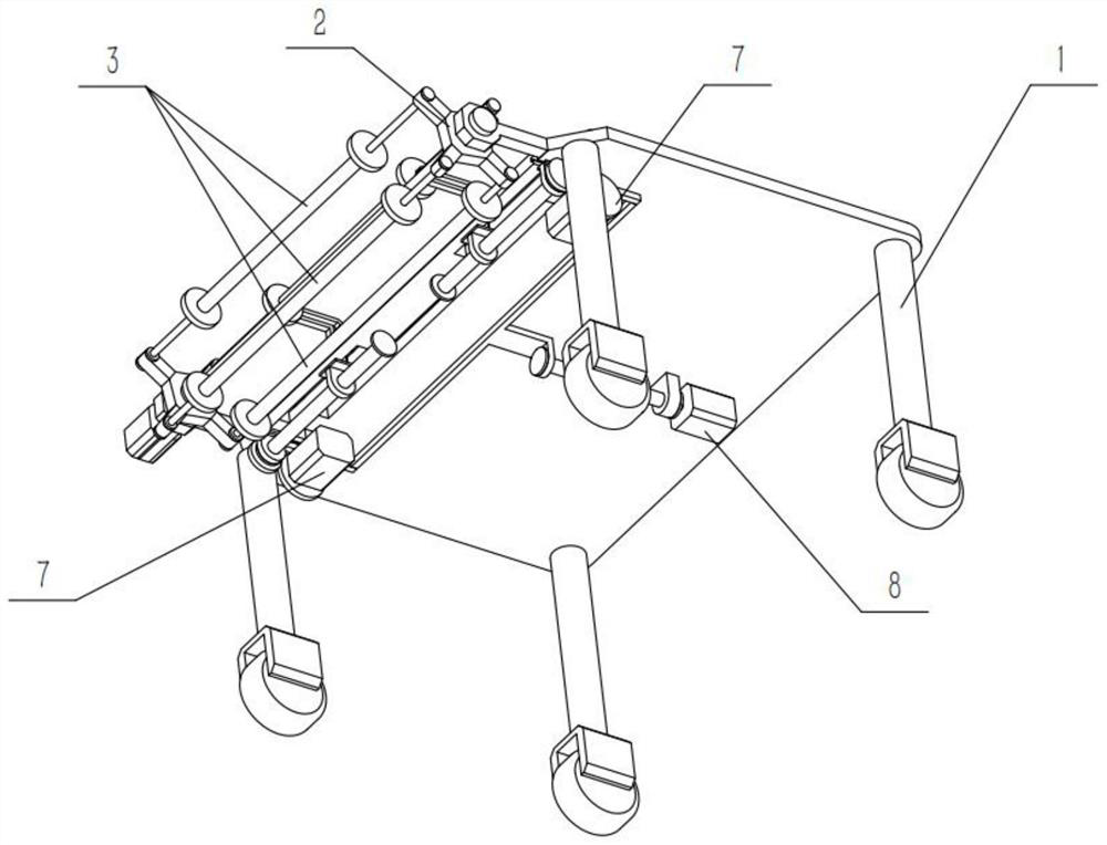
[0033] Combine below Figure 1-10Describe this embodiment, a cloth cutting machine for garment processing, including an operating table 1 and a transition rod 4, the transition rod 4 is rotatably connected to the front side of the operating table 1, and the cloth cutting machine for clothing processing also includes a turntable 2 , cloth roller 3, sliding positioning mechanism 5, cloth pressing plate 6, motor II 7, drive mechanism 8 and control button 9, said turret 2 is rotatably connected to the front end of said console 1, and said cloth roller 3 is provided with four , four distributing rollers 3 are evenly rotated and connected to the turntable 2, and the sliding positioning mechanism 5 is provided with two, and the two positioning mechanisms 5 are respectively slidingly connected to the left and right sides of the front end of the operating table 1, two The lower end of the positioning mechanism 5 is fixedly connected to the motor II 7, and the cloth pressing plate 6 is ...

specific Embodiment approach 2

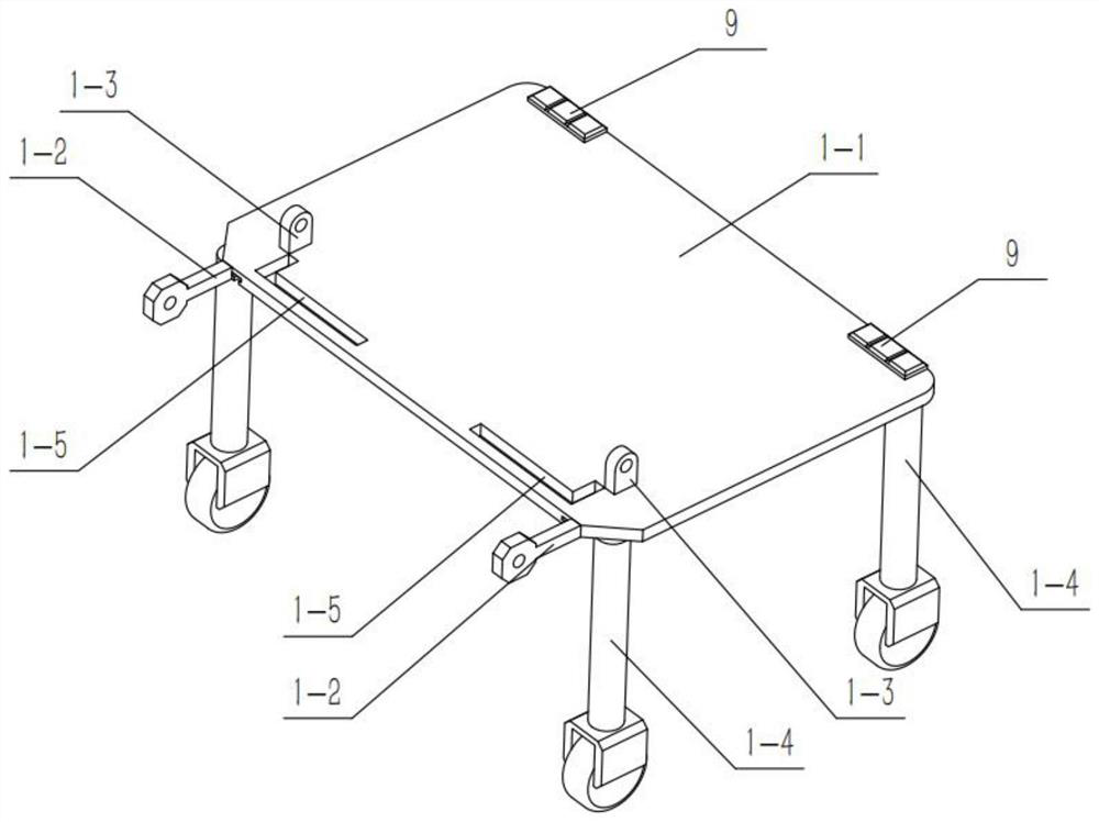
[0035] Combine below Figure 1-10 Describe this embodiment, this embodiment will further explain Embodiment 1, the operating table 1 includes an operating panel 1-1, a connecting arm 1-2, an ear plate I 1-3, a leg 1-4, and an L-shaped chute 1-5, the chute 1-6 and the ear plate II 1-7, the four legs 1-4 are provided, and the four legs 1-4 are fixedly connected to the lower surface of the operation panel 1-1 respectively. At the four corners, the lower end of each supporting leg 1-4 is provided with universal wheels, and the connecting arms 1-2 are provided with two, and the two connecting arms 1-2 are fixedly connected to the operating panel surface 1-1 respectively. On the left and right sides of the front end, two ear plates I1-3 are symmetrically arranged on the left and right sides of the front part of the operation panel surface 1-1, and two L-shaped ear plates are symmetrically arranged on the front part of the operation panel surface 1-1. There are two chute 1-5, the ch...

specific Embodiment approach 3

[0037] Combine below Figure 1-10 Describe this embodiment, this embodiment will further illustrate the second embodiment, the turntable 2 includes a rotating shaft 2-1, a side plate 2-2, a motor I 2-3 and a rod 2-4, and the side plate 2-2 There are two side plates 2-2 fixedly connected to the left and right sides of the rotating shaft 2-1 respectively, the output shaft of the motor I2-3 is fixedly connected to one end of the rotating shaft 2-1, the There are four rods 2-4, the left and right ends of the four rods 2-4 are evenly and fixedly connected to the two side plates 2-2 respectively, and the four distributing rollers 3 are respectively connected to the four rods 2-4 in rotation, The motor I2-3 is fixedly connected to the connecting arm 1-2 on the corresponding side, and the motor I2-3 has a brake function.


PUM


Abstract

The present invention relates to the technical field of garment processing, and more specifically to a fabric cutting machine for garment processing. Before the cutting starts, the fabric rolls with different fabrics to be used can be placed on different bars of the turntable, and then press The button on the control button controls the motor Ⅰ, put the bar that needs to use the cloth roller against the positioning groove at the front end of the two bending plates, and then pull the cloth on the cloth roller by hand, and use the inner side of the two cloth pressing plates The inner pressure plate sticks the side of the fabric to the operating table to facilitate the cutting of the fabric. The cutting staff can pull out the appropriate length of the fabric according to the demand, so as to facilitate the cutting and save time. Fix the relative position of other cloth rollers for cutting, and control the bending plate through two motors II according to the cutting habit to adjust the relative position of the cloth rollers, which is convenient for the cutting work of cutting workers.

Description

technical field [0001] The invention relates to the technical field of garment processing, in particular to a cloth cutting machine for garment processing. Background technique [0002] In the flat cutting process of clothing, the cutter usually places the fabric on a flat table, and cuts after drawing the cutting marks. In the actual cutting process, the cutter needs to choose different sizes according to the parts and sizes of the clothing to be made. different fabrics or cut and switch between different fabrics according to actual needs, while the existing cutting table can only perform simple cutting work, the fabric roller and the cutting table are placed separately, if you need different sizes of fabrics or different kinds of fabrics For the conversion, it is necessary to take out the required fabric rollers, measure and cut them. In the fabric cutting that needs to frequently cut different sizes and different fabrics, it is cumbersome and time-consuming to manually ta...

Claims


Application Information

Patent Timeline
Patent Type & Authority Patents(China)
IPC IPC(8): D06H7/00
CPCD06H7/00
Inventor 林洁
Owner 吴江桑尚丝绸有限公司
Learn More