
Light-emitting diode aftertreatment process

A light-emitting diode and post-processing technology, which is applied in the direction of electrical components, circuits, semiconductor devices, etc., can solve the problems of unsatisfactory production, waste of raw materials, and low work efficiency, and achieve high straightening efficiency, improved effect, and good effect.

Active Publication Date: 2020-06-16
深圳市世鸿鑫科技有限公司
View PDF7 Cites 3 Cited by
  • Summary
  • Abstract
  • Description
  • Claims
  • Application Information

AI Technical Summary

Problems solved by technology

[0003] However, the existing light-emitting diode pins have the following problems when they are straightened: a, when the traditional light-emitting diode pins are straightened, it is necessary to manually hold the middle end of the light-emitting diode, and hold the pins of the light-emitting diode with your fingers to stroke Straight work, low work efficiency, can not meet a large number of production, and it is easy to be stabbed by the pins of the light-emitting diodes when manually straightening the fingers; b, when the pins of the light-emitting diodes are straightened manually, due to excessive force, often Pulling off the pins of the light-emitting diodes is a waste of raw materials, and it can stably straighten the pins of the light-emitting diodes. The operation is simple, the straightening efficiency is high and the effect is good, and the pins will not be broken.

Method used


Image

  • Light-emitting diode aftertreatment process
  • Light-emitting diode aftertreatment process
  • Light-emitting diode aftertreatment process

Examples


Embodiment Construction

[0031] The embodiments of the present invention will be described in detail below with reference to the accompanying drawings, but the present invention can be implemented in many different ways defined and covered by the claims.

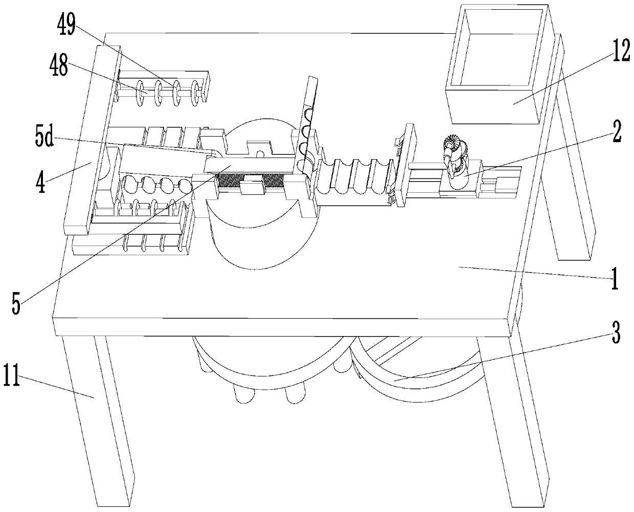
[0032] Such as Figure 1 to Figure 9 As shown, a light-emitting diode post-treatment process mainly includes the following steps:

[0033] Step 1, inspection operation: artificial light-emitting diodes perform light-emitting inspection operations to obtain qualified light-emitting diodes;

[0034] Step 2, straightening process: put the light-emitting diodes that have passed the inspection in step 1 into the straightening device to straighten the pins of the light-emitting diodes to obtain a complete light-emitting diode;

[0035]Step 3, detection processing: the complete light-emitting diode obtained in step 2 is subjected to light-emitting detection processing again to obtain a complete light-emitting diode;

[0036] Step 4, collecting and packag...


PUM


Abstract

The invention relates to a light-emitting diode aftertreatment process. The light-emitting diode aftertreatment process mainly comprises the following multiple procedures of inspection operation, straightening treatment, detection treatment, collection packaging and the like. Adopted straightening equipment comprises a bottom plate, a taking device, a rotating device, a straightening device and aclamping device. The following problems existing during straightening of an existing light-emitting diode pin that a, when the traditional light-emitting diode pin is straightened, the middle end of alight-emitting diode needs to be manually held, the pin of the light-emitting diode is clamped by fingers to be straightened, consequently the work efficiency is low, mass production cannot be met, and when straightening is conducted manually through the fingers, the fingers are prone to being stabbed by the pin of the light-emitting diode; and b, when being straightened manually, the pin of thelight-emitting diode is often pulled cut due to excessive force, and consequently raw materials are wasted can be solved; and the straightening efficiency is high, the straightening effect is good, and the phenomenon that the pin is pulled cut is avoided.

Description

technical field [0001] The invention relates to the technical field of electrical component manufacturing and processing, in particular to a light-emitting diode post-treatment process. Background technique [0002] Light-emitting diodes are referred to as LEDs for short. Light-emitting diodes are a commonly used light-emitting device that releases energy through the recombination of electrons and holes to emit light. Diodes, flashing light-emitting diodes, voltage-controlled light-emitting diodes, infrared light-emitting diodes, and negative-resistance light-emitting diodes, etc., light-emitting diodes can efficiently convert electrical energy into light energy, and have a wide range of uses in modern society, such as lighting, flat panel displays, medical devices etc., the light emitting diode can be used again, but the lead of the light emitting diode for secondary use is often bent, and the lead of the light emitting diode needs to be straightened. [0003] However, the...

Claims


Application Information

Patent Timeline
IPC IPC(8): B21F1/02H01L33/62H01L21/67
CPCB21F1/02H01L21/67138H01L33/62
Inventor 倪娅丹高亚芳
Owner 深圳市世鸿鑫科技有限公司
Learn More