Eureka AIR delivers breakthrough ideas for toughest innovation challenges, trusted by R&D personnel around the world.

A self-clearing submersible pump

A submersible pump and self-cleaning technology, applied in the direction of pumps, pump components, pump devices, etc., can solve the problems of taking a long time, dangerous for clearing personnel, and the submersible pump cannot pump water normally, so as to improve the effect of clearing blockage and clear the water. High blocking efficiency

Active Publication Date: 2020-12-22
HANGZHOU SILAITE PUMP CO LTD
View PDF6 Cites 0 Cited by
  • Summary
  • Abstract
  • Description
  • Claims
  • Application Information

AI Technical Summary

Problems solved by technology

[0003] Since the underwater conditions of rivers, reservoirs or canals are relatively complicated, and there are many aquatic plants, silt and other sundries, when the impeller of the submersible pump generates negative pressure, it is easy to suck the above sundries in the water body to the water inlet. The opening area is generally small, so the debris cannot enter the pump body and will be stuck in the water inlet. After a period of accumulation, the newly pumped debris and the previously pumped into the water inlet and stuck and discharged debris will accumulate in the water inlet. , block the water inlet, so that the submersible pump cannot pump water normally
[0004] When the water inlet of the submersible pump is blocked, if the blockage is not cleaned in time, the submersible motor will be idle for a long time, which will affect the service life of the submersible motor. At the same time, if the blockage is not cleaned in time, the water in production will not be supplied in time , will affect the normal production and life, and in the prior art, artificial diving into the bottom of the water is usually used to clear the blockage. This way of cleaning the blockage first needs to find the working fault of the submersible pump, and then arrange for professionals to clear the blockage, and the professionals dive into the bottom of the water It also takes a long time, so this blockage removal method is not only inefficient, but also has certain dangers for the blockage removal personnel.

Method used


Image

  • A self-clearing submersible pump
  • A self-clearing submersible pump

Examples


Embodiment Construction

[0020] The following will clearly and completely describe the technical solutions in the embodiments of the present invention with reference to the accompanying drawings in the embodiments of the present invention. Obviously, the described embodiments are only some, not all, embodiments of the present invention.

[0021] In describing the present invention, it should be understood that the terms "upper", "lower", "front", "rear", "left", "right", "top", "bottom", "inner", " The orientation or positional relationship indicated by "outside", etc. is based on the orientation or positional relationship shown in the drawings, and is only for the convenience of describing the present invention and simplifying the description, rather than indicating or implying that the referred device or element must have a specific orientation, so as to Specific orientation configurations and operations, therefore, are not to be construed as limitations on the invention.

[0022] refer to Figure ...


PUM


Abstract

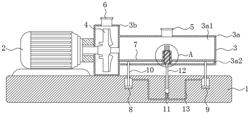
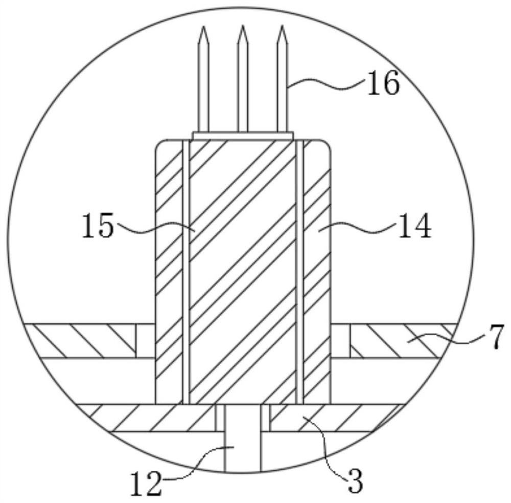
The invention discloses a self-dredging submersible pump. The self-dredging submersible comprises a base, a pump body and a submersible motor, wherein the pump body is fixedly arranged at an upper endof the base; the pump body comprises a pump body water inlet end and a pump body water outlet end; a water inlet and a water outlet are formed at upper ends of the pump body water inlet end and the pump body water outlet end respectively; and an output shaft of the submersible motor passes through the pump body water outlet end. Through the arrangement of a dredging mechanism, a driving mechanismand a pushing mechanism, a slide bar can be pushed up by air pressure when the water inlet end of the submersible pump is blocked, thereby driving a threaded rod to move upwards. Meanwhile, the threaded rod rotates under the action of a sleeve to drive a dredging fork to rotate, thereby realizing the simultaneous rising and rotating actions of the dredging fork, clearing barriers at the water outlet, enabling the submersible pump to work normally, and realizing rapid dredging and relatively high efficiency. Meanwhile, manual dredging is not required, and danger of dredging workers at work areavoided. Meanwhile, the submersible pump does not need to be stopped, and great impact on production is avoided.

Description

technical field [0001] The invention relates to the technical field of submersible pump accessories, in particular to a self-clearing submersible pump. Background technique [0002] Submersible pumps can be used in water lifting projects such as rivers, reservoirs, and canals. When in use, the entire unit submerges into the water to extract water from rivers, reservoirs, or canals to the surface for farmland irrigation and human and livestock use in high mountain areas. [0003] Since the underwater conditions of rivers, reservoirs or canals are relatively complicated, and there are many aquatic plants, silt and other sundries, when the impeller of the submersible pump generates negative pressure, it is easy to suck the above sundries in the water body to the water inlet. The opening area is generally small, so the debris cannot enter the pump body and will be stuck in the water inlet. After a period of accumulation, the newly pumped debris and the previously pumped into the...

Claims


Application Information

Patent Timeline
Patent Type & Authority Patents(China)
IPC IPC(8): F04D13/08F04D29/00F04D29/70F04D7/04
CPCF04D7/045F04D13/08F04D29/007F04D29/708
Inventor 徐玉霞邹思娟
Owner HANGZHOU SILAITE PUMP CO LTD
Why Eureka
Eureka Blog
Learn More