
Compressor and refrigeration equipment

A compressor and frame technology, applied in the field of compressors, can solve problems such as compressor failure, displacement, frame deformation, etc., and achieve the effect of improving reliability

Active Publication Date: 2020-06-12
ANHUI MEIZHI COMPRESSOR
View PDF9 Cites 4 Cited by
  • Summary
  • Abstract
  • Description
  • Claims
  • Application Information

AI Technical Summary

Problems solved by technology

However, this method needs to set multiple anti-collision bumps on the frame to avoid collisions in different directions, and cannot avoid direct collision between the frame and the shell. When the rigidity of the frame is weak, the gap between the frame and the shell Direct collision is not allowed, it will cause deformation and displacement of the frame, resulting in failure of the compressor

Method used


Image

  • Compressor and refrigeration equipment
  • Compressor and refrigeration equipment
  • Compressor and refrigeration equipment

Examples


Embodiment 1

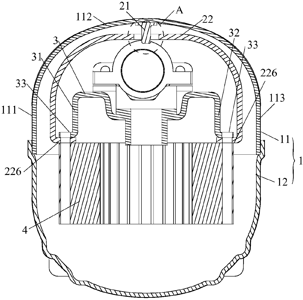
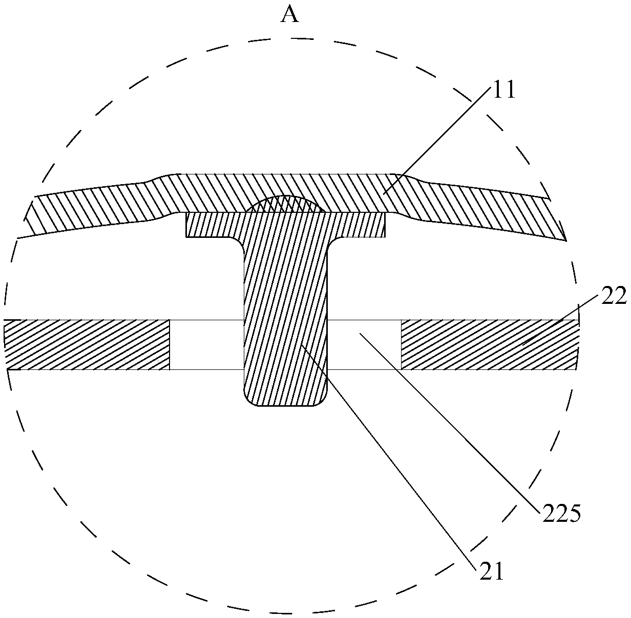
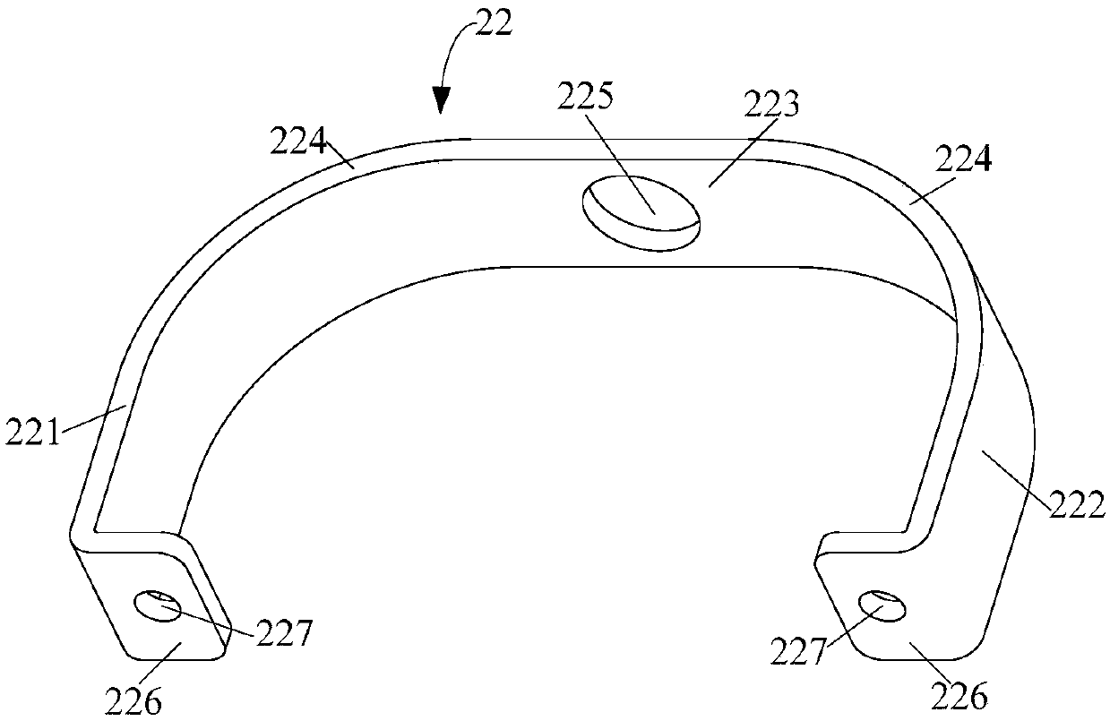
[0046] Such as figure 1 with figure 2 As shown, a compressor 100 provided according to some embodiments of the present invention includes a casing 1 , a frame 3 and an anti-collision assembly. The housing 1 defines the installation space; the frame 3 is located in the installation space; the anti-collision assembly includes an anti-collision frame 22 and an anti-collision protrusion 21, the anti-collision frame 22 is arranged between the frame 3 and the housing 1, and the anti-collision frame 22 and one of the housing 1 is provided with an anti-collision hole 225, and the other is provided with an anti-collision protrusion 21, and the anti-collision protrusion 21 is clearance-fitted in the anti-collision hole 225.

[0047] In the compressor 100 provided by the above embodiments of the present invention, the anti-collision frame 22 is arranged between the casing 1 and the frame 3, the casing 1 is provided with an anti-collision protrusion 21, and the anti-collision frame 22 i...

Embodiment 2

[0074] The difference from Embodiment 1 is that the anti-collision frame 22 is provided with an anti-collision protrusion 21, and the housing 1 is provided with an anti-collision hole 225, and the anti-collision protrusion 21 and the anti-collision hole 225 are arranged correspondingly, and the anti-collision protrusion 21 One end of the anti-collision protrusion 21 is connected to the anti-collision frame 22, and the other end of the anti-collision protrusion 21 is located in the anti-collision hole 225 and fits with the anti-collision hole 225 in clearance.

[0075] The embodiment of the second aspect of the present invention provides a refrigeration device, including the compressor 100 according to any one of the embodiments of the first aspect.

[0076] To sum up, the anti-collision component can prevent the collision between the frame and the shell in any direction, and can make the reciprocating compressor play an anti-collision protection role for the frame during transp...


PUM


Abstract

The invention provides a compressor and refrigeration equipment. The compressor comprises a shell, a rack and an anti-collision assembly. An installing space is defined by the shell. The rack is located in the installing space. The anti-collision assembly comprises an anti-collision frame and an anti-collision protrusion, the anti-collision frame is arranged between the rack and the shell, one ofthe anti-collision frame and the shell is provided with an anti-collision hole, the other one of the anti-collision frame and the shell is provided with the anti-collision protrusion, and the anti-collision protrusion is in clearance fit in the anti-collision hole. According to the provided compressor, when a pump body of the compressor greatly swings, the anti-collision protrusion makes contact with the inner wall face of the anti-collision hole, accordingly, the anti-collision protection function is achieved for the rack, and reliability of the compressor is improved; and the anti-collisionprotrusion is in clearance fit with the anti-collision hole, and therefore collisions between the rack and the shell in multiple directions can be prevented.

Description

technical field [0001] The present invention relates to the technical field of compressors, and more specifically, to a compressor and refrigeration equipment including the compressor. Background technique [0002] The existing compressor structure includes a shell and a pump body located inside the shell. The compressor will shake a lot during transportation or start and stop, which will cause the pump body and the shell to collide and cause key components to fail, or even The pump body is out of spring, causing the compressor to fail to operate normally. [0003] In order to improve this situation, the common method is to set anti-collision bumps on the frame of the pump body. During the collision, these anti-collision bumps will collide with the shell, avoiding the collision of key components and the shell, and also This prevents the pump body from being out of spring due to excessive freedom. However, this method needs to set multiple anti-collision bumps on the frame ...

Claims


Application Information

Patent Timeline
Patent Type & Authority Applications(China)
IPC IPC(8): F04B39/12
CPCF04B39/121
Inventor 束洋宋东东
Owner ANHUI MEIZHI COMPRESSOR
Learn More