
Water saving device

A technology of water-saving device and water-saving valve, which is applied in water supply devices, water supply devices, indoor sanitary piping devices, etc., can solve the problems of hot water cooling and cooling, troublesome use, easy to cause the life of sealing rubber rings, etc. sealing effect

Pending Publication Date: 2020-06-12
CHANGSHU GAOTONG INTELLECT EQUIP CO LTD
View PDF0 Cites 0 Cited by
  • Summary
  • Abstract
  • Description
  • Claims
  • Application Information

AI Technical Summary

Problems solved by technology

[0002] The washbasin is generally placed at home or in a public place for washing. A hot and cold water switch for adjusting the temperature of the water outlet is installed on the washbasin. The hot and cold water switch is connected to the hot water source and the cold water source respectively through two water pipes; When the water switch is turned on to release hot water, the water in the water pipe connected between the hot water switch and the hot water source stops flowing in this section of water pipe for a long time, causing the hot water in this section of water pipe to dissipate heat and become cold. When using water, the cold water in this section of the water pipe will flow out first, and sometimes people will release the water in this section of the water pipe for convenience, resulting in waste of water resources
[0003] The mop pool is a kind of equipment used to clean the mop. When using it, you need to put water in the mop pool in advance. After use, you need to bend down and manually pull out the plunger on the lower side of the mop pool to let the sewage go. more troublesome
[0004] On the other hand, the plunger switch at the drain of the mop pool can easily cause the life of its sealing rubber ring due to long-term contact with sewage.

Method used


Image

  • Water saving device
  • Water saving device
  • Water saving device

Examples


Embodiment Construction

[0053] The specific implementation manners of the present invention will be further described in detail below in conjunction with the accompanying drawings and embodiments. The following examples or drawings are used to illustrate the present invention, but not to limit the scope of the present invention.

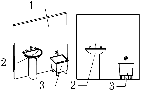
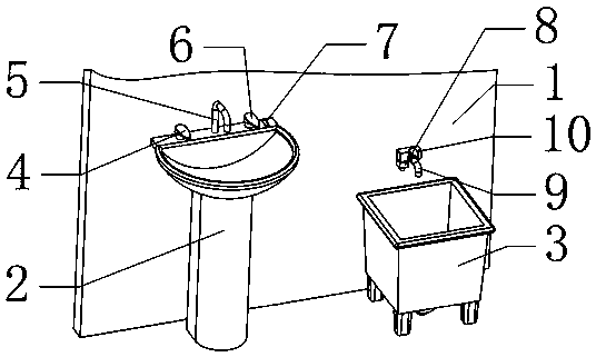
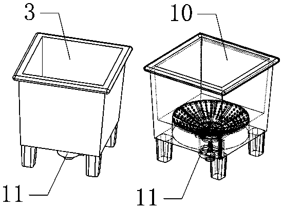
[0054] like figure 1 , 2 As shown, it includes a washbasin 2 and a mop pool 3, wherein the washbasin 2 is installed on the installation wall 1, and the washbasin 2 is equipped with a hot and cold water switch 4 and a washbasin outlet pipe 5, and the washbasin outlet pipe 5 is connected to the hot and cold The water outlet of the water switch 4 is connected through a water pipe, the cold water inlet of the hot and cold water switch 4 is connected with the cold water source through a cold water pipe, and the hot water inlet of the hot and cold water switch 4 is connected with the hot water source through a hot water pipe; A water outlet switch 10 is installed on the water p...


PUM


Abstract

The invention belongs to the technical field of water saving, and particularly relates to a water saving device. The water saving device comprises a wash basin and a mop tub. According to the water saving device by design, when a cold and hot water faucet on the wash basin is turned on to discharge hot water, water in the part, connected between a hot water inlet of the cold and hot water faucet and a hot water source, of a hot water pipe stays and flows in the section of the water pipe for a long time, so that the hot water in the section of the water pipe is subjected to hear dissipation andgets cold; when the hot water is discharged, the cooled water in the section of water pipe can flow out preferentially, and sometimes, people tend to make the water in the section of water pipe flowaway for convenience, so that water source waste is caused; and before the cold and hot water faucet is turned on to discharge the hot water, the control switch is turned on firstly, so that the waterstaying and flowing in the part, connected between the hot water inlet of the cold and hot water faucet and the hot water source, of the hot water pipe flows out and flows into the mop tub through the control switch and a water outlet pipe of the mop tub to be stored for cleaning a mop.

Description

technical field [0001] The invention belongs to the technical field of water saving, and in particular relates to a water saving device. Background technique [0002] The washbasin is generally placed at home or in a public place for washing. A hot and cold water switch for adjusting the temperature of the water is installed on the washbasin. The hot and cold water switch is connected to the hot water source and the cold water source respectively through two water pipes; When the water switch is turned on to release hot water, the water in the water pipe connected between the hot water switch and the hot water source stops flowing in this section of water pipe for a long time, causing the hot water in this section of water pipe to dissipate heat and become cold. When watering, the cold water in this section of the water pipe will flow out preferentially, and sometimes people will release the water in this section of the water pipe for convenience, resulting in a waste of wat...

Claims


Application Information

Patent Timeline
Patent Type & Authority Applications(China)
IPC IPC(8): E03C1/02E03C1/04E03B1/04E03B7/04E03B7/07
CPCE03C1/02E03C1/04E03B1/041E03B1/04E03B7/04E03B7/07E03B2001/045Y02A20/411
Inventor 陈姿红张明
Owner CHANGSHU GAOTONG INTELLECT EQUIP CO LTD
Learn More