Power amplifier case with adjustable local heat dissipation capacity

A heat-dissipating, adjustable technology, used in electrical equipment structural parts, cooling/ventilation/heating renovation, chassis/cabinet/drawer parts, etc. The problems such as the accumulation of differences and complex processing can be achieved to ensure the electromagnetic sealing performance, reduce the flow resistance, and improve the heat exchange effect.

Pending Publication Date: 2020-06-09
NO 54 INST OF CHINA ELECTRONICS SCI & TECH GRP
View PDF0 Cites 1 Cited by
  • Summary
  • Abstract
  • Description
  • Claims
  • Application Information

AI Technical Summary

Problems solved by technology

However, when the liquid channel under each power tube is connected in series, since the temperature of the liquid rises after absorbing heat, the temperature of the power tube that flows through the liquid later will be higher than the temperature of the power tube that flows through the liquid first, resulting in a temperature difference between different power tubes Gradually accumulate and increase; when the liquid flow channel adopts parallel connection, the more the number of power tubes, the more difficult it is to distribute the flow in each branch evenly, and it will also cause the volume and weight of the cold plate to increase, the processing is complicated, and the yield is low.
[0005] To sum up, once the heat dissipation chassis is manufactured and the temperature consistency cannot meet the requirements, the local heat dissipation capacity of the power tube cannot be adjusted, that is, the actual temperature of a single power tube cannot be independently adjusted.

Method used


Image

  • Power amplifier case with adjustable local heat dissipation capacity
  • Power amplifier case with adjustable local heat dissipation capacity
  • Power amplifier case with adjustable local heat dissipation capacity

Examples


Embodiment Construction

[0021] Below, the present invention will be further described in conjunction with the accompanying drawings and specific embodiments.

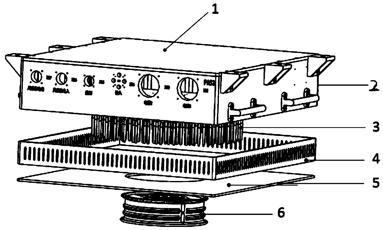
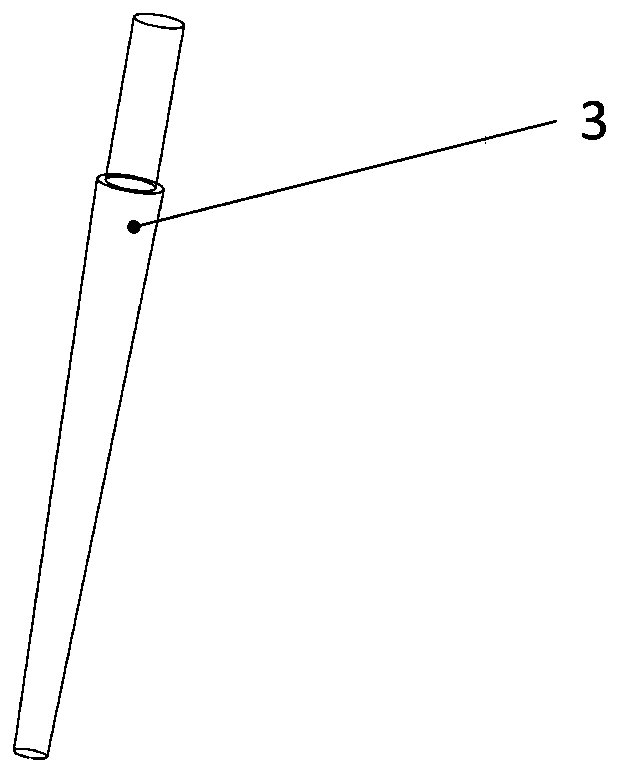
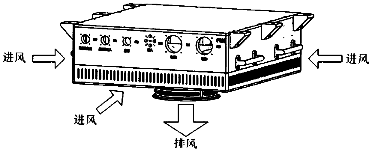
[0022] A power amplifier case with adjustable local heat dissipation capacity, which includes an upper equipment chamber and a lower heat dissipation chamber, the equipment chamber and the heat dissipation chamber are separated by a mounting plate; a plurality of power tubes are arranged on one side of the equipment chamber of the mounting plate Mounting position, one side of the heat dissipation cavity of the mounting plate, at the corresponding position of each power tube installation position, there is at least one connection hole; at least one connection hole in the heat dissipation cavity is provided with a heat dissipation column, and the heat dissipation column and the connection hole Threaded connection; a vent is provided on the side wall of the heat dissipation chamber, and a heat dissipation fan is provided on the bottom plate of the...


PUM


Abstract

The invention discloses a power amplifier case with adjustable local heat dissipation capacity, and belongs to the technical field of cases. The case comprises an equipment cavity located on the upperpart and a heat dissipation cavity located on the lower part, wherein the equipment cavity and the heat dissipation cavity are separated through a mounting plate; a plurality of power tube mounting positions are arranged on one side of the equipment cavity of the mounting plate, and at least one connecting hole is formed in the position, which corresponds to each power tube mounting position, ofone side of the heat dissipation cavity of the mounting plate; at least one connecting hole in the heat dissipation cavity is provided with a heat dissipation column, and the heat dissipation column is in threaded connection with the connecting hole; and a ventilation opening is formed in the side wall of the heat dissipation cavity, and a heat dissipation fan is arranged on a bottom plate of theheat dissipation cavity. According to the invention, the heat dissipation area is increased, the heat exchange effect is further improved, and the local heat dissipation capacity can be adjusted by increasing or decreasing the number of the heat dissipation columns and changing the assembly positions of the heat dissipation columns.

Description

technical field [0001] The invention relates to the technical field of cabinets, in particular to a power amplifier cabinet with adjustable local heat dissipation capacity. Background technique [0002] High-power solid-state power amplifier extensions generally use multiple power tubes for power synthesis. The commonly used synthesis system is radial power synthesis, that is, multiple power tubes are distributed along a circle of a certain diameter on a plane. When the actual temperature of each power tube is working, the difference should not be too large, otherwise it will affect the synthesis efficiency and the index of the power amplifier extension. Therefore, at this time, each power tube is required to meet the heat dissipation index and temperature consistency. [0003] The first commonly used solution is to adopt an air-cooled heat dissipation system, and heat pipes, vapor chambers or other high thermal conductivity materials are embedded on the power tube mounting...

Claims


Application Information

Patent Timeline
Patent Type & Authority Applications(China)
IPC IPC(8): H05K7/14H05K7/20H05K5/02H05K5/03H05K5/06
CPCH05K5/0217H05K5/0247H05K5/03H05K5/061H05K7/1417H05K7/20145H05K7/20154H05K7/20172
Inventor 谢明君
Owner NO 54 INST OF CHINA ELECTRONICS SCI & TECH GRP
Why Eureka
Try Eureka