
Weldless lightweight battery box body and manufacturing process thereof

A lightweight, no-weld technology, applied to battery pack parts, circuits, electrical components, etc., can solve the problems of reduced material performance of side beams, low production efficiency, large product deformation, etc., and it is easy to control the dimensional accuracy, Effects of improving cost and efficiency and reducing equipment cost

Pending Publication Date: 2020-06-09
纽维科精密制造江苏有限公司
View PDF0 Cites 2 Cited by
  • Summary
  • Abstract
  • Description
  • Claims
  • Application Information

AI Technical Summary

Problems solved by technology

[0003] In the existing box structure, most of the frame profiles are processed and welded first by fusion welding, and then connected to the bottom by friction stir welding. Welding (5~10 meters), not only long working hours, but also high cost, large product deformation, poor stability, low production efficiency, and difficult to control
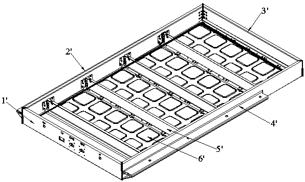
[0004] as attached figure 1 As shown, after the front frame 1', the left frame 2', the rear frame 3' and the right frame 4' are assembled, the 4 corners are melt welded, and the full welding length is 1.5~3 meters (depending on the size and height of the box), The length and width will shrink by 0.5~1.0mm, and the size is not easy to control; the beam 5' is connected to the frame by fusion welding (TIG or CMT), the material performance of the side beam will be reduced, there is a risk of welding through, and at the same time it will shrink and deform. The processed module holes will be offset; the existing process of bottom plate 6' and frame is friction stir welding
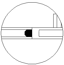
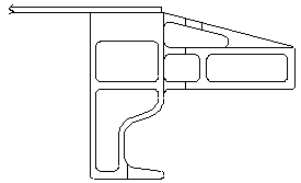
[0005] like figure 2 As shown, the existing scheme 1 uses hollow profiles, such as image 3 As shown, the existing scheme 2 uses a single-layer bottom plate, which is currently the most reliable in terms of manufacturability and airtightness. The main problem is that the welds are relatively long, and more equipment is required for increased production capacity.

Method used


Image

  • Weldless lightweight battery box body and manufacturing process thereof
  • Weldless lightweight battery box body and manufacturing process thereof
  • Weldless lightweight battery box body and manufacturing process thereof

Examples


Embodiment Construction

[0061] The following will clearly and completely describe the technical solutions in the embodiments of the present invention. Obviously, the described embodiments are only some of the embodiments of the present invention, rather than all the embodiments. Based on the embodiments of the present invention, all other embodiments obtained by persons of ordinary skill in the art without making creative efforts belong to the protection scope of the present invention.

[0062] see Figure 4 to Figure 18 , the embodiment of the present invention includes:

[0063] A lightweight battery box without welds, comprising: a frame profile, a frame corner 700, a beam 500 and a bottom plate 600, the frame profile is assembled through the frame corner 700 to form a frame group, the beam 500 is installed horizontally inside the frame group and Locked with the left and right sides of the frame group, the bottom plate 600 is buckled on the frame group and locked and fixed with the frame group. ...


PUM


Abstract

The invention discloses a weldless lightweight battery box body and a manufacturing process thereof. The weldless lightweight battery box body comprises frame profiles, frame corner connectors, crossbeams and a bottom plate, wherein the frame profiles are assembled together through the frame corner connectors to form a frame set, the cross beams are transversely installed in the frame set and locked with the left side and the right side of the frame set, and the bottom plate is connected to the frame set in a buckled mode and locked and fixed with the frame set; the frame set is sequentiallysubjected to the steps of coating the frame corner connectors with adhesive, inserting the frame corner connectors into one frame, inserting the frame corner connectors into the other frame, clamping,screw assembling, adhesive supplementing or smearing and curing; the cross beams are sequentially subjected to pre-fixing, structural adhesive coating, assembling and curing; and the bottom plate issequentially subjected to adhesive coating, adhering and FDS riveting. According to the weldless lightweight battery box and the manufacturing process thereof, large-area fusion welding and stirring welding can be removed, the cost and the efficiency are greatly improved, the size precision is easy to control, the deformation is avoided, the equipment cost is reduced, the adhesive coating processand the FDS process are used together, and high feasibility of an automatic production line is guaranteed.

Description

technical field [0001] The invention relates to the technical field of auto parts, in particular to a lightweight battery box without welds and a manufacturing process thereof. Background technique [0002] In recent years, the new energy vehicle industry has developed rapidly, and aluminum extrusion profiles have been widely used in new energy vehicle battery trays to improve the lightweight level of new energy vehicles. [0003] In the existing box structure, most of the frame profiles are processed and welded first by fusion welding, and then connected to the bottom by friction stir welding. Welding (5-10 meters), not only long working hours, but also high cost, large product deformation, poor stability, low production efficiency, and difficult to control. [0004] as attached figure 1 As shown, after the front frame 1', the left frame 2', the rear frame 3' and the right frame 4' are assembled, the 4 corners are melt welded, and the full welding length is 1.5~3 meters (...

Claims


Application Information

Patent Timeline
IPC IPC(8): H01M2/10H01M50/249
CPCH01M50/20Y02E60/10
Inventor 徐海东刘伟
Owner 纽维科精密制造江苏有限公司
Learn More