Knob and knob control method

A control method and knob technology, applied in the field of knobs, can solve problems such as low adjustability, single control function of knobs, wear of sealing rings, etc., and achieve good sealing effect, flexible adjustment, and improved convenience

Active Publication Date: 2020-06-09
NINGBO FOTILE KITCHEN WARE CO LTD
View PDF14 Cites 0 Cited by
  • Summary
  • Abstract
  • Description
  • Claims
  • Application Information

AI Technical Summary

Problems solved by technology

However, the radial seal between the knob and the panel is mainly realized in this structure. During long-term use, with the continuous use of the knob, the sealing ring will be worn, thereby reducing the sealing performance between the knob and the panel.
In addition, the control function of the knob is single. When using the knob to adjust the gear, especially when the adjustment gear is large, it needs to rotate a large angle to realize the adjustment of the large gear. The unit adjustment variable of the knob is fixed, and the adjustability is low.

Method used


Image

  • Knob and knob control method
  • Knob and knob control method
  • Knob and knob control method

Examples


Embodiment Construction

[0031] The present invention will be further described in detail below in conjunction with the accompanying drawings and embodiments.

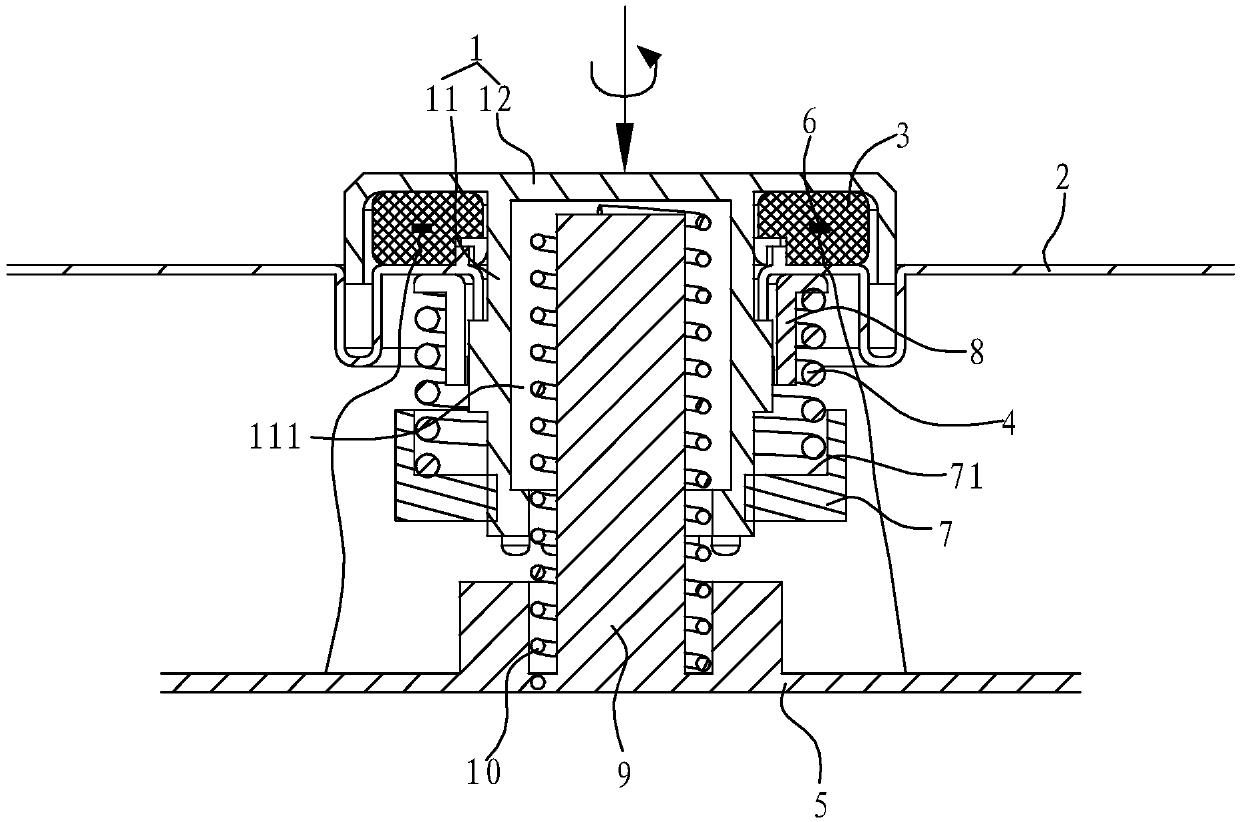
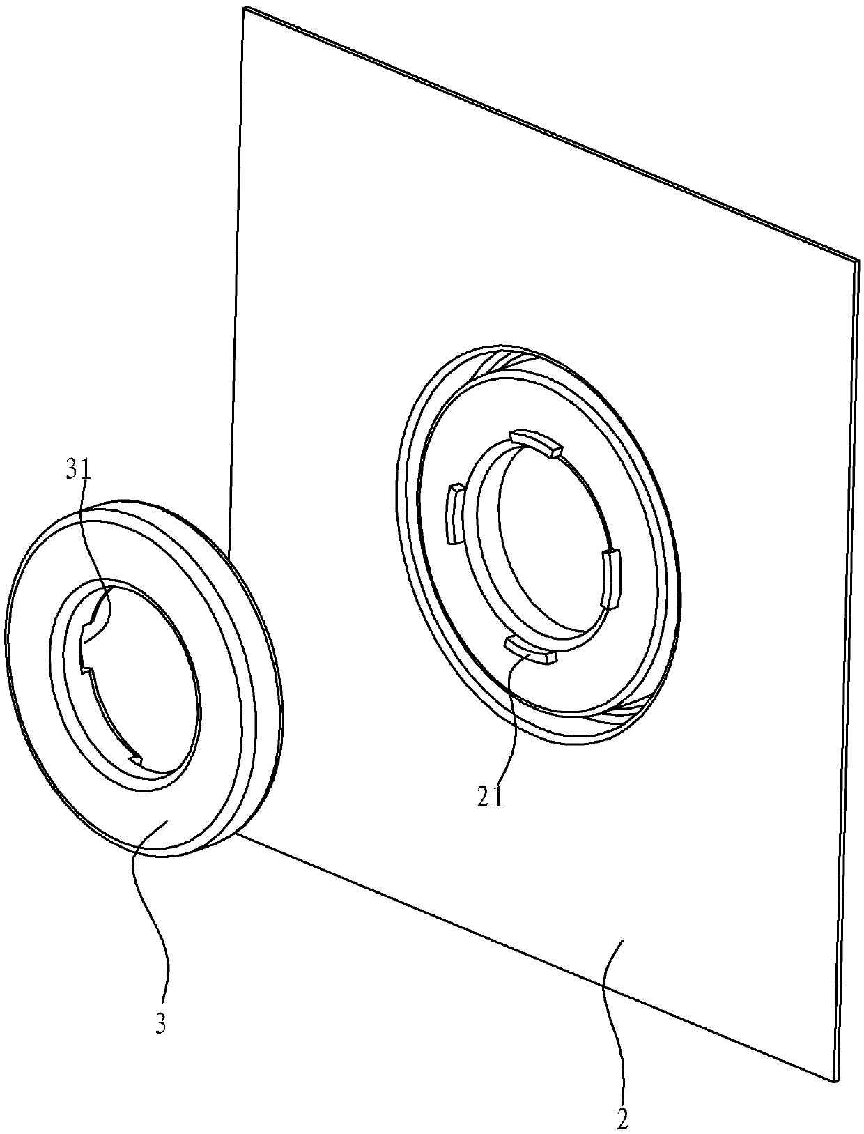
[0032] Such as Figure 1 to Figure 4 As shown, the knob in this embodiment includes a rotating body 1 , a gasket 3 , an elastic member 4 , a support member 7 , a washer 8 , and a circuit board 5 .

[0033] The rotating body 1 includes a cylinder 11 inserted in the mounting hole of the panel 2 and a screw cover 12 connected to the top of the cylinder 11. The screw cover 12 in this embodiment includes a base plate and a set extending downward from the outer edge of the base plate. side panels. The panel 2 is provided with a groove corresponding to the side board, and the lower end of the side board can be deeply inserted into the groove, so that waterproofing can be further realized. At the same time, space is provided for the axial movement of the rotating body 1 .

[0034] The gasket 3 is arranged in the space surrounded by the base plate, ...


PUM


Abstract

The invention relates to a knob. The knob comprises a rotating body, wherein the rotating body comprises a column body inserted into a panel mounting hole, a screw cap connected with the top of the column body and a sealing gasket arranged between a lower end surface of the screw cap and the panel, the column body is sleeved with an elastic piece, a first end of the elastic piece is pressed on a lower end surface of the panel, and a second end of the elastic piece is pressed on the column body so that the rotating body has the tendency of moving downwards. The knob is advantaged in that the end surface of the screw cap is sealed through the rotary knob, and the sealing effect is better. Even if an end surface of a sealing gasket is abraded, a problem of sealing failure does not occur. Theinvention further relates to a control method of the knob. The pressure V borne by the knob is detected and obtained through a pressure sensor. V is compared with a pressure threshold range Vi corresponding to each unit rotation angle adjustment quantity Mi, wherein i is a natural number, if V falls into the range of Vi, that the unit rotation angle adjustment amount of the knob is Mi is determined, so adjustability of the knob is high.

Description

technical field [0001] The invention relates to a knob, and also relates to a method for controlling the knob. Background technique [0002] Knobs are used in various electrical appliances. When installing the knob on a panel, in order to ensure the sealing of the installation on the panel, a sealing ring is usually provided between the knob and the panel. For example, in the Chinese utility model patent "Induction Cooker and Knob Device" with the authorized announcement number CN202813494U (application number 201220382148.2), a sealing ring is provided between the disclosed knob and the panel, thereby preventing external water from entering the interior of the electrical appliance through the knob. , to further prevent the internal electronic components from being corroded or burned by water, thereby improving the safety performance and service life of electrical appliances. However, in this structure, the radial seal between the knob and the panel is mainly realized. Duri...

Claims


Application Information

Patent Timeline
Patent Type & Authority Applications(China)
IPC IPC(8): G05G1/10
CPCG05G1/10
Inventor 谭洵黄启彬金晶梁稳刘筱倩陈茂军周高云
Owner NINGBO FOTILE KITCHEN WARE CO LTD
Why Eureka
Try Eureka