
Magnetic resonance imaging method, device, storage medium and medical equipment

A technology of magnetic resonance imaging and magnetic resonance imaging, which is applied in the directions of magnetic resonance measurement, measurement using nuclear magnetic resonance imaging system, measurement device, etc., which can solve the problems of difficult to eliminate streak artifacts, low imaging quality, and slow imaging speed. , to reduce motion artifacts, improve imaging quality, and eliminate streak artifacts

Active Publication Date: 2022-05-17
SHANGHAI NEUSOFT MEDICAL TECH LTD +1
View PDF0 Cites 0 Cited by
  • Summary
  • Abstract
  • Description
  • Claims
  • Application Information

AI Technical Summary

Problems solved by technology

However, the disadvantage of MRI is that the imaging speed is slow, and the compressed sensing (CS) method samples far below the Nyquist frequency, so it can greatly improve the imaging speed, and has received extensive attention from researchers in recent years.
[0003] At present, MRI methods based on compressed sensing are mainly divided into two categories according to the coordinate system of the sampling trajectory: methods based on Cartesian coordinate system (such as k-t SPARSE-SENSE method, PS-Sparse method) and methods based on non-Cartesian coordinate system The method based on the Cartesian coordinate system (such as the iGRASP method), and the method based on the Cartesian coordinate system is susceptible to motion artifacts due to the time difference between the acquisition of the data in the central area of ​​K-space and the data in the outer periphery of K-space. Although the method of the coordinate system is not sensitive to motion, the streak artifacts in the image are difficult to eliminate. It can be seen that the imaging quality of the magnetic resonance imaging method based on compressed sensing in related technologies is not high

Method used


Image

  • Magnetic resonance imaging method, device, storage medium and medical equipment
  • Magnetic resonance imaging method, device, storage medium and medical equipment
  • Magnetic resonance imaging method, device, storage medium and medical equipment

Examples


Embodiment Construction

[0042] Reference will now be made in detail to the exemplary embodiments, examples of which are illustrated in the accompanying drawings. When the following description refers to the accompanying drawings, the same numerals in different drawings refer to the same or similar elements unless otherwise indicated. The implementations described in the following exemplary embodiments do not represent all implementations consistent with this application. Rather, they are merely examples of apparatuses and methods consistent with aspects of the present application as recited in the appended claims.

[0043] The terminology used in this application is for the purpose of describing particular embodiments only, and is not intended to limit the application. As used in this application and the appended claims, the singular forms "a", "the", and "the" are intended to include the plural forms as well, unless the context clearly dictates otherwise. It should also be understood that the term...


PUM


Abstract

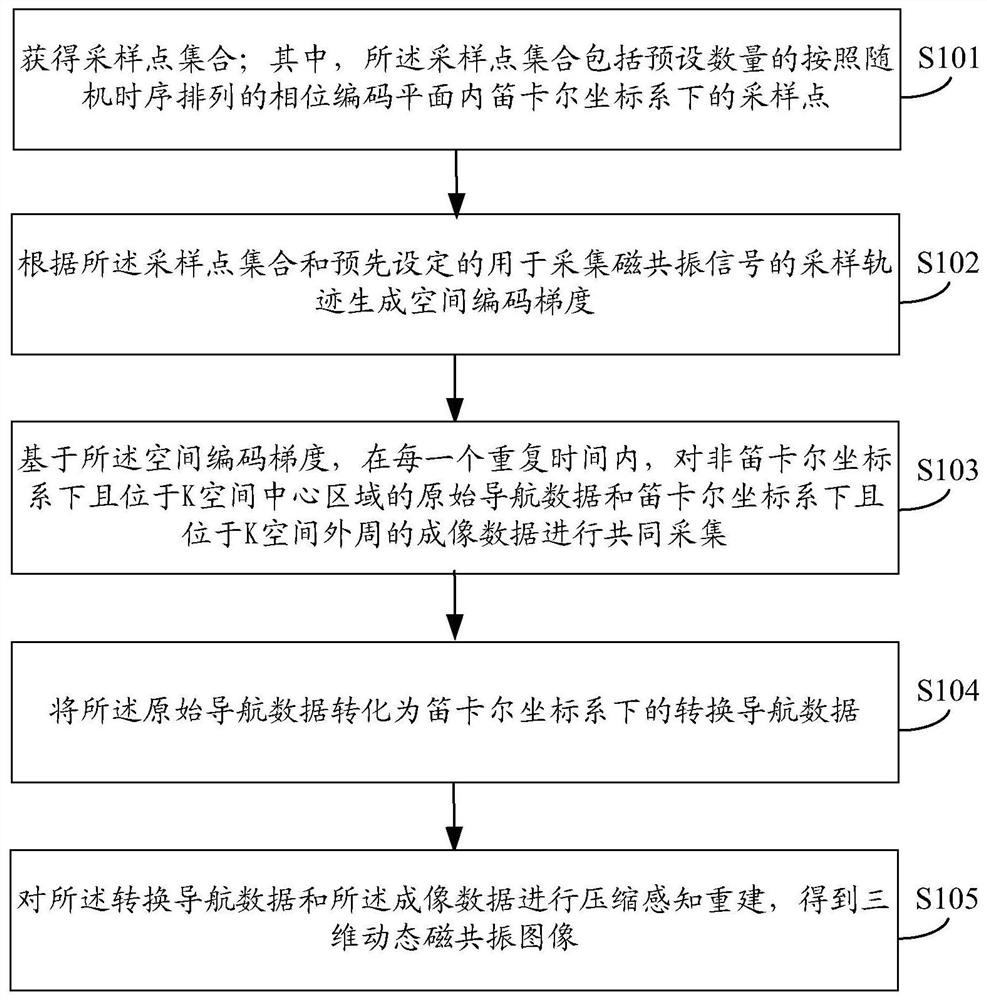
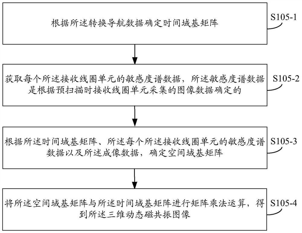
The present application provides a magnetic resonance imaging method, device, storage medium and medical equipment to improve imaging quality. The magnetic resonance imaging method includes: obtaining a sampling point set; wherein, the sampling point set includes a preset number of sampling points in a Cartesian coordinate system in a phase encoding plane arranged according to a random time sequence; The set sampling trajectory for acquiring the magnetic resonance signal generates a spatial encoding gradient; based on the spatial encoding gradient, in each repetition time, the original navigation data and the The imaging data in the Karl coordinate system and located in the outer periphery of the K-space are jointly collected; the original navigation data is converted into the converted navigation data in the Cartesian coordinate system; compressed sensing reconstruction is performed on the converted navigation data and the imaging data, Three-dimensional dynamic magnetic resonance images were obtained.

Description

technical field [0001] The present application relates to the technical field of magnetic resonance imaging, in particular to a magnetic resonance imaging method, device, storage medium and medical equipment. Background technique [0002] Magnetic resonance imaging (MRI) uses the principle of magnetic resonance imaging to enable people to obtain detailed diagnostic images of living organs and tissues without damage. However, the disadvantage of MRI is that the imaging speed is slow, and the compressed sensing (CS) method samples far below the Nyquist frequency, so it can greatly improve the imaging speed, and has attracted extensive attention from researchers in recent years. [0003] At present, MRI methods based on compressed sensing are mainly divided into two categories according to the coordinate system of the sampling trajectory: methods based on Cartesian coordinate system (such as k-t SPARSE-SENSE method, PS-Sparse method) and methods based on non-Cartesian coordinat...

Claims


Application Information

Patent Timeline
Patent Type & Authority Patents(China)
IPC IPC(8): G01R33/48G01R33/56A61B5/055
CPCG01R33/4822G01R33/4826G01R33/5608A61B5/055A61B5/72
Inventor 孙爱琦
Owner SHANGHAI NEUSOFT MEDICAL TECH LTD
Learn More