Signal acquisition system for surface acoustic wave magnetic sensor

A signal acquisition system and magnetic sensor technology, applied in the direction of the size/direction of the magnetic field, using magneto-optical equipment for magnetic field measurement, instruments, etc., can solve the problem that small changes in the SAW resonance frequency are difficult to be detected, and the output frequency range of the signal generator Limited, high-frequency SAW devices are difficult to start vibration, etc., to achieve the effect of no test blind zone, simple structure, and high circuit stability

Pending Publication Date: 2020-06-09
XI AN JIAOTONG UNIV
View PDF0 Cites 3 Cited by
  • Summary
  • Abstract
  • Description
  • Claims
  • Application Information

AI Technical Summary

Problems solved by technology

In this method, due to fluctuations in the frequency of the DDS excitation signal, small changes in the SAW resonance frequency are sometimes difficult to detect, that is, there is a blind area for sensing signal detection
Although the phase / amplitude detection method does not involve frequency measurement, due to the limited output frequency range of the signal generator, it is difficult for high-frequency SAW devices to vibrate, and the range of detection signals is limited
Moreover, the circuit structure of this method is complicated, which is not conducive to the detection of the sensor array, and it is difficult to apply in practice.

Method used


Image

  • Signal acquisition system for surface acoustic wave magnetic sensor
  • Signal acquisition system for surface acoustic wave magnetic sensor
  • Signal acquisition system for surface acoustic wave magnetic sensor

Examples


Embodiment Construction

[0026] The present invention is further described below in conjunction with accompanying drawing:

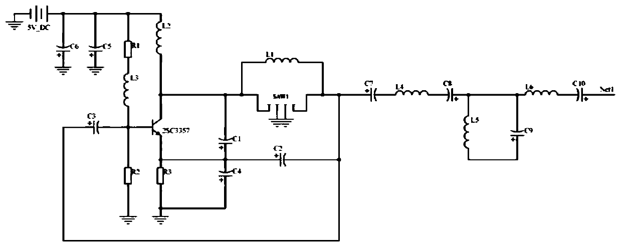
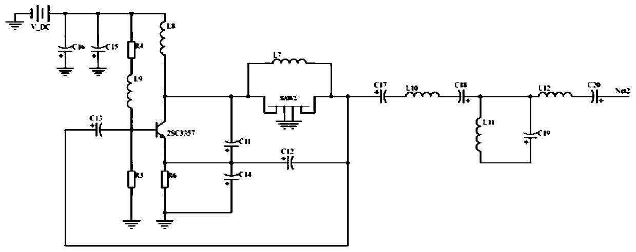
[0027] like figure 1 As shown, the present invention includes oscillating circuits 1 and 2, a frequency mixing circuit 3, an amplification and shaping circuit 4, and a frequency measurement circuit 5 connected in sequence; the first input end of the frequency mixing circuit 3 is connected to output the oscillation of the SAW sensor measurement frequency signal Circuit 1, the second input end of the frequency mixing circuit 3 is connected to the oscillation circuit 2 outputting the SAW sensor reference frequency signal; the amplification and shaping circuit 4 is connected to the signal output terminal IF of the frequency mixing circuit 3; the frequency measurement circuit 5 is mainly composed of chip STM32F103C8T6, the 16th pin of the chip STM32F103C8T6 is connected to the signal output end of the amplification and shaping circuit 4, the chip STM32F103C8T6 can communicate with th...


PUM


Abstract

The invention discloses a signal acquisition system for a surface acoustic wave magnetic sensor. The signal acquisition system comprises a first oscillating circuit, a second oscillating circuit, a mixer circuit, an amplifying and shaping circuit and a single-chip microcomputer frequency measuring circuit, the first input end of the mixer circuit is connected with the first oscillating circuit, and the second input end of the mixer circuit 3 is connected with the second oscillating circuit; the amplifying and shaping circuit is connected with the signal output end IF of the frequency mixing circuit; the frequency measuring circuit is mainly connected with the signal output end of the amplifying and shaping circuit; the first oscillating circuit and the second oscillating circuit are used for outputting SAW sensor measuring frequency signals. According to the invention, a Pierce type oscillating circuit is adopted, and a SAW sensor is easy to perform self-excited oscillating to output asinusoidal signal with a specific frequency. Furthermore, the magnetic field intensity can be measured through a single difference value, namely the change of the signal frequency of a measuring branch. The precision is high, the detection range is wide, and no test blind area exists.

Description

technical field [0001] The invention belongs to the technical field of signal acquisition systems, and particularly relates to a signal acquisition system for a surface acoustic wave magnetic sensor. Background technique [0002] Surface Acoustic Wave (SAW) is an elastic wave propagating along the surface of a solid. Through the interdigital transducer structure, surface acoustic waves can be excited and detected on the surface of piezoelectric materials. The magnetostrictive film (FeCo, NiFe, Metglas, etc.) is introduced into the interdigital transducer. Under the action of the external magnetic field, the Young's modulus of the magnetostrictive material changes, and the surface acoustic wave velocity also changes, so as to achieve detection. The purpose of the weak magnetic field. The magnetic field sensitivity of the reported high-Q SAW resonator can reach more than 150Hz / μT, and the detection limit can reach nT / Hz 1 / 2 magnitude. Compared with other magnetic field sen...

Claims


Application Information

Patent Timeline
IPC IPC(8): G01R33/032G01R33/00
CPCG01R33/0023G01R33/0327
Inventor 刘明胡忠强王志广周子尧吴金根杜泳君
Owner XI AN JIAOTONG UNIV
Why Eureka
Try Eureka