Roof beam building structure and construction method

A technology for building structures and beams, applied in building construction, construction, building materials processing, etc., can solve problems such as single installation of auxiliary crossbars, adjust the inclination angle of inclined beams, and affect roof laying, etc., and achieve stable connection. , Guarantee the effect of flatness and efficient construction

Inactive Publication Date: 2020-06-09
浙江省建筑科学设计研究院有限公司
View PDF6 Cites 1 Cited by
  • Summary
  • Abstract
  • Description
  • Claims
  • Application Information

AI Technical Summary

Problems solved by technology

[0003] However, the existing beam structure is relatively simple, and the triangular main structure is formed by welding directly with steel, which is not conducive to adjusting the inclination angle of the inclined beam according to the needs, and the adaptability is poor. Moreover, when the main beam is connected, the installation method of the auxiliary beam Relatively single, it is easy to cause interference during construction and affect subsequent roof laying, and its structure and construction methods need to be improved

Method used


Image

  • Roof beam building structure and construction method
  • Roof beam building structure and construction method
  • Roof beam building structure and construction method

Examples


Embodiment 1

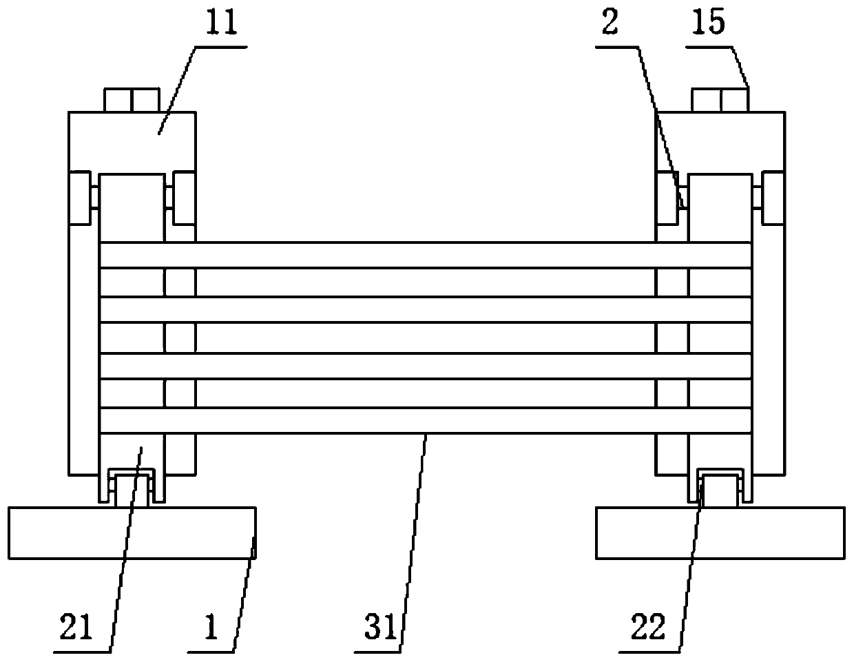
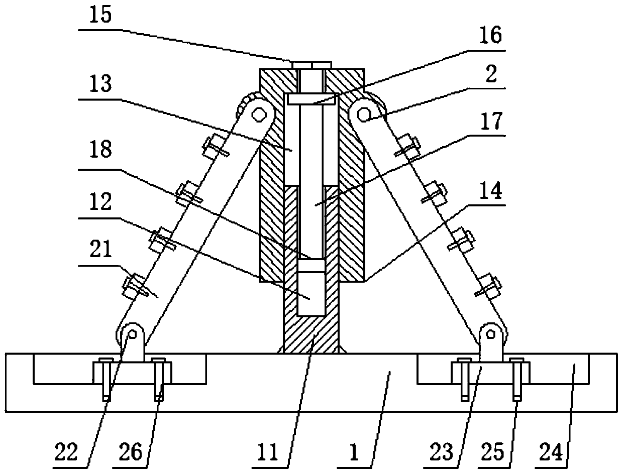
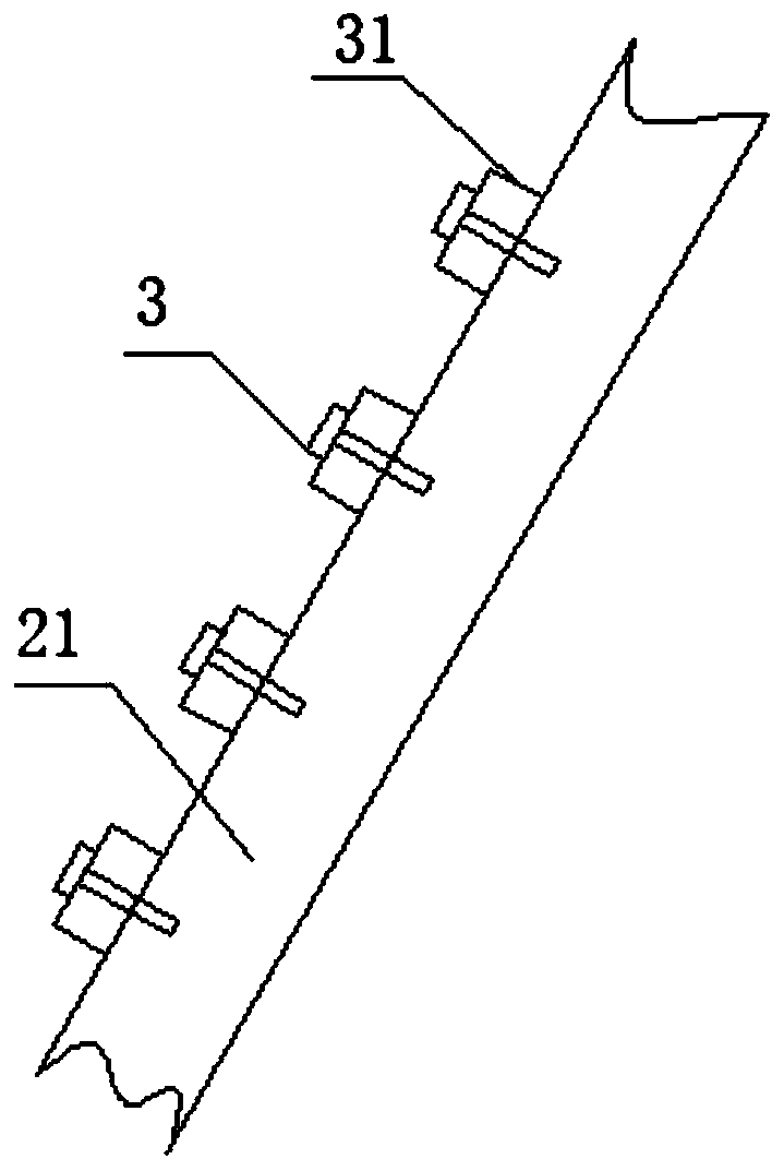
[0047] see figure 2 and image 3 , the upper end of the outer surface of the inclined beam 21 is fixedly installed with the first auxiliary cross bar 31 through the first bolt 3, and the first auxiliary cross bar 31 is connected to the outer surface of the inclined beam 21 at equal intervals, after the inclined beam 21 fixes the angular position , the first auxiliary rods 31 are equidistantly installed on the upper surface of the inclined beam 21 through the first bolts 3, which is convenient for connection and use, stable and efficient.

Embodiment 2

[0049] see figure 2 and Figure 4 , the outer surface side of the inclined beam 21 is fixedly welded with the second auxiliary cross bar 33 through the welding seam 32, and the second auxiliary cross bar 33 is evenly connected between the two inclined beams 21 at equal intervals, so that the angular position of the inclined beam 21 can be fixed Finally, the second auxiliary cross bar 33 is butted to the side position between the two inclined beams 21, and then welded and fixed, which can ensure the stability of the structural frame and at the same time ensure the flatness of the upper surface of the inclined beams 21, which is conducive to laying the roof , high adaptability.

Embodiment 3

[0051] see figure 2 and Figure 5 , the outer upper end of the inclined beam 21 is provided with an auxiliary groove 34, the inner surface of the auxiliary groove 34 is fixedly connected with a third auxiliary cross bar 35, and the upper surface of the inclined beam 21 is fixedly installed with a fixed pressure plate 37 through a second bolt 36, The lower surface of the fixed pressure plate 37 is fixedly pressed and connected to the upper surface of the third auxiliary cross bar 35, after the angle position of the inclined beam 21 is fixed, an auxiliary groove 34 is pre-set on the inclined beam 21, and then the third auxiliary cross bar The two ends of the rod 35 are placed inside the auxiliary groove 34 of the inclined beam 21, which can be placed stably, and then the second bolt 36 is used to fix and install the fixed pressure plate 37, so that the third auxiliary cross bar 35 can be pressed into the auxiliary groove 34 , to avoid prolapse and improve the stability of conn...


PUM


Abstract

The invention discloses a roof beam building structure. The roof beam building structure comprises two cross beams. Supporting columns are fixedly welded to the centers of upper surfaces of the crossbeams, adjusting threaded holes are formed in the upper surfaces of the supporting columns, adjusting columns are slidably mounted on the outer surfaces of the supporting columns through adjusting holes, the upper ends in the adjusting columns are rotatably connected with operating heads, the lower surfaces of the operating heads are fixedly connected with supporting plates, the upper surfaces ofthe supporting plates are in pulling connection to the upper surfaces in the adjusting holes, the lower surfaces of the supporting plates are fixedly connected with adjusting rods, the lower surfacesof the adjusting rods are fixedly connected with thread heads, the outer surfaces of the thread heads are in threaded connection with the inner surfaces of the adjusting threaded holes, and two sidesof the outer surfaces of the adjusting columns are hinged to inclined beams through jointed shafts, so that the using convenience and stability can be improved greatly and the using safety and high efficiency are guaranteed.

Description

technical field [0001] The invention relates to the field of house beam structures, more specifically, to a house beam building structure and a construction method. Background technique [0002] In the current building construction process, the use of equipment-type beam structures is becoming more and more common, and it can be constructed separately from the wall to effectively improve efficiency. [0003] However, the existing beam structure is relatively simple, and the triangular main structure is formed by welding directly with steel, which is not conducive to adjusting the inclination angle of the inclined beam according to the needs, and the adaptability is poor. Moreover, when the main beam is connected, the installation method of the auxiliary beam Relatively simple, it is easy to cause interference during construction and affect subsequent roof laying, and its structure and construction methods need to be improved. Contents of the invention [0004] Aiming at t...

Claims


Application Information

Patent Timeline
Patent Type & Authority Applications(China)
IPC IPC(8): E04G21/18
CPCE04G21/1841
Inventor 李蓉樱诸宏博
Owner 浙江省建筑科学设计研究院有限公司
Why Eureka
Try Eureka