
A Helicopter Rotor Blade Variation Lower Reverse Tip Drive Mechanism Based on Centrifugal Mass Block

A helicopter rotor, centrifugal mass technology, applied in the direction of rotorcraft, motor vehicles, wing adjustment, etc., can solve the problems of difficult to provide driving power tip, large recovery torque, narrow blade space, etc., to ensure safety, reduce Small overall size, the effect of reducing demand

Active Publication Date: 2022-08-05
NANJING UNIV OF AERONAUTICS & ASTRONAUTICS
View PDF5 Cites 0 Cited by
  • Summary
  • Abstract
  • Description
  • Claims
  • Application Information

AI Technical Summary

Problems solved by technology

The main reason is that the propeller tip works in a very large centrifugal force field and complex aerodynamic environment, and the space of the propeller blade is narrow, and the recovery torque generated after the propeller tip is reversed is relatively large, which makes it difficult for the general drive mechanism to provide sufficient drive. power to achieve active control of the propeller tip

Method used


Image

  • A Helicopter Rotor Blade Variation Lower Reverse Tip Drive Mechanism Based on Centrifugal Mass Block
  • A Helicopter Rotor Blade Variation Lower Reverse Tip Drive Mechanism Based on Centrifugal Mass Block
  • A Helicopter Rotor Blade Variation Lower Reverse Tip Drive Mechanism Based on Centrifugal Mass Block

Examples


Embodiment Construction

[0031] In order to clearly illustrate the technical features of the present patent, the present patent will be described in detail below through specific embodiments and in conjunction with the accompanying drawings.

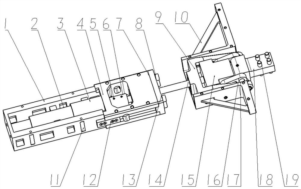
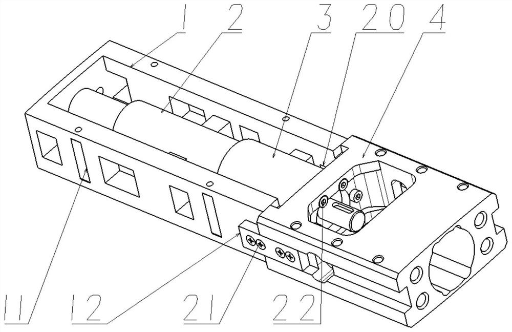
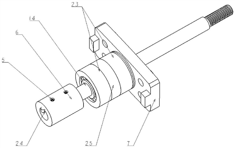
[0032] The present invention is as Figure 1-9 As shown, the rotor blade of the helicopter includes a blade base 33 and a blade tip 36 provided at one end of the blade base, and the lower anti-drive mechanism includes a driver unit and a blade tip actuator unit, and the driver unit is connected to the The blade base body, the blade tip actuator unit is respectively connected with the blade base body and the blade tip, and the blade tip actuator unit is reciprocated and flipped under the drive of the driver unit to realize the change of the lower reverse angle.

[0033] The blade tip actuator unit includes a centrifugal mass 15, a linkage assembly and a blade tip actuating head 18;

[0034] The centrifugal mass 15 is slidably connected in the blade base 33 and i...


PUM


Abstract

A centrifugal mass-based helicopter rotor blade under-reverse propeller tip drive mechanism. The invention belongs to the intelligent rotor technology in the field of helicopter rotor vibration and noise control. A driving mechanism that can stably drive the propeller tip of the helicopter under a large centrifugal force field and a complex aerodynamic environment, so as to change the size of the reverse angle under the propeller tip according to the different flight states of the helicopter, is proposed. The technical solution of the present invention is as follows: the lower anti-driving mechanism includes a driver unit and a blade tip actuator unit, the driver unit is connected to the blade base body, and the blade tip actuator unit is respectively connected to the blade base body and the blade tip actuator unit. The tips are connected, and the tip actuator unit is reciprocated and flipped under the drive of the driver unit, so as to realize the change of the lower reverse angle. Under certain flight conditions, the downward reaction of the propeller tip will suppress the BVI by weakening the propeller tip vortex and increasing the vertical distance between the propeller tip vortex and the subsequent blades, so as to achieve the purpose of reducing noise and vibration of the rotor.

Description

technical field [0001] The invention belongs to the intelligent rotor technology in the field of helicopter rotor vibration and noise control, and in particular relates to active control suitable for helicopter blade tips. Background technique [0002] Compared with fixed-wing aircraft, helicopters have special flight capabilities such as vertical take-off and landing and hovering in the air. These unique flight capabilities make them widely used in military and civilian fields. With the continuous development of helicopter technology, the Blade Vortex Interaction (BVI) problem of helicopter rotors has received extensive attention. When the propeller vortex interference occurs, not only the vibration level of the propeller blade will increase, but also a strong BVI noise with significant acoustic characteristics will be formed. In order to reduce the BVI strength, many advanced propeller tips adopt the structure of the lower reverse propeller tip, the main purpose of which ...

Claims


Application Information

Patent Timeline
Patent Type & Authority Patents(China)
IPC IPC(8): B64C27/32B64C3/38F16C35/00H02K7/06
CPCB64C27/32B64C3/38F16C35/00H02K7/06
Inventor 董凌华郑庆卓杨卫东
Owner NANJING UNIV OF AERONAUTICS & ASTRONAUTICS
Learn More