
Cam drive mechanism and offset press with same

A driving mechanism and cam technology, applied in rotary printing presses, offset rotary printing presses, printing, etc., can solve the problems of socket wear, difficult disassembly, large gap between the pin and socket, etc., to ensure assembly stability and complete rotation. Synchronized, easily removable effects

Active Publication Date: 2020-06-09
江西丰彩丽印刷包装有限公司
View PDF11 Cites 0 Cited by
  • Summary
  • Abstract
  • Description
  • Claims
  • Application Information

AI Technical Summary

Problems solved by technology

[0004] However, in the existing cam drive mechanism, the cam is usually welded on the wheel shaft, so that the cam and the wheel shaft cannot be disassembled and adjusted, so that the damaged cam cannot be replaced or the cam of different specifications can be replaced according to different printing requirements. The cam that has appeared is detachably installed on the wheel shaft, usually with a pin structure, that is, the pin is inserted into the hole provided on the cam and the wheel shaft, but because there is a gap between the hole and the pin (if there is a gap between the hole and the pin) If there is an interference fit between the cam and the axle, it is still extremely difficult to disassemble), resulting in a slight deviation of the cam when the axle rotates and cannot be completely synchronized, which seriously affects the printing quality. The holes are all worn out, resulting in an increasing gap between the pin and the socket after use

Method used


Image

  • Cam drive mechanism and offset press with same
  • Cam drive mechanism and offset press with same
  • Cam drive mechanism and offset press with same

Examples


Embodiment 1

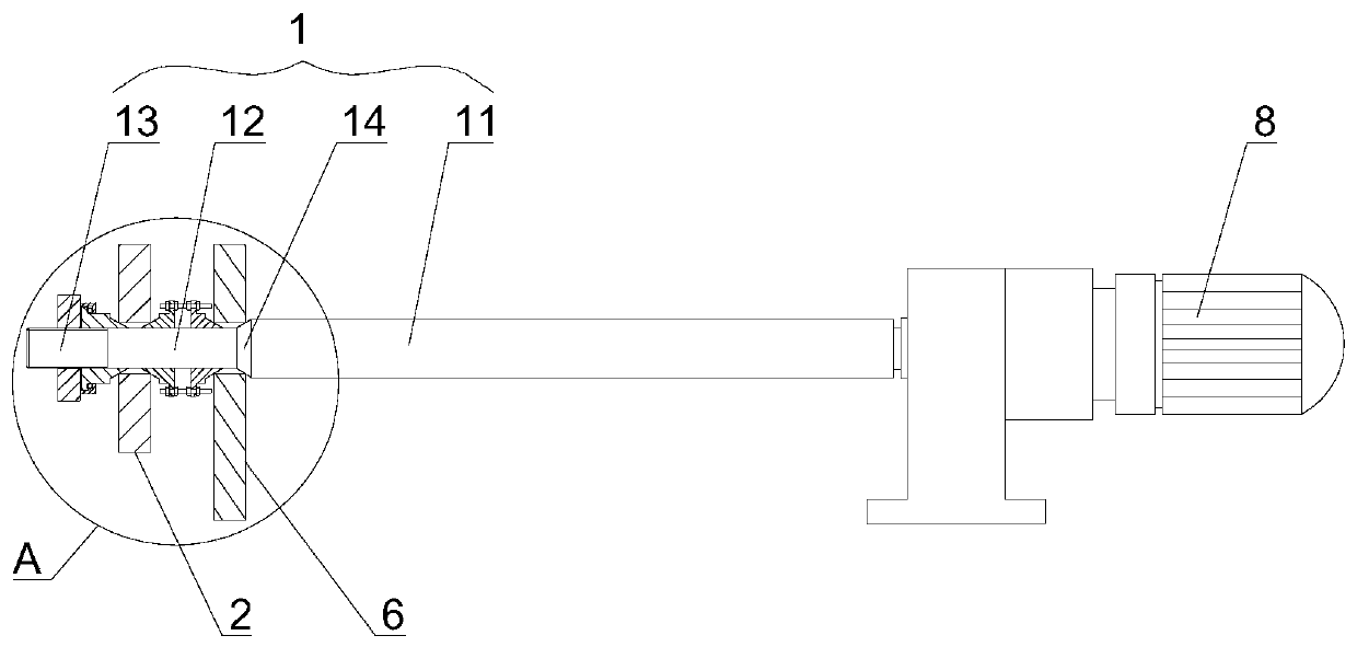
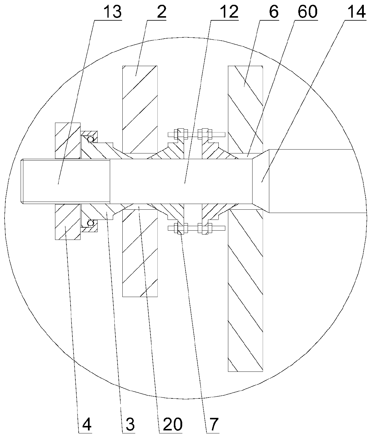
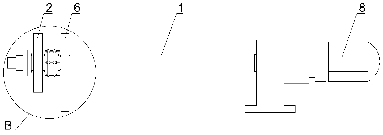
[0034] like Figure 1 to Figure 11 As shown, a cam driving mechanism provided in this embodiment includes a wheel shaft 1 , a first cam 2 , an expansion taper sleeve 3 , and a locking screw sleeve 4 . The axle 1 includes a main section 11 , an assembly section 12 , and a threaded section 13 sequentially arranged along the same axis. The assembly section 12 is located between the main section 11 and the threaded section 13 . The main section 11 , the assembly section 12 , and the threaded section 13 are integrated. The first cam 2 is provided with a first assembly through hole 20 that runs through the first cam 2, and the first cam 2 is sleeved on the assembly section 12 through the first assembly through hole 20. The shape of the first assembly through hole 20 is the same as that of the assembly section. The shape of 12 is adapted to ensure the consistency and continuity of the gap formed between the first assembly through hole and the assembly section, so as to facilitate the...

Embodiment 2

[0045] The difference between embodiment 2 and embodiment 1 is:

[0046] The cam driving mechanism also includes a second cam 6 and a double-headed expansion taper sleeve 7. The second cam 6 is provided with a second assembly through hole 60 passing through the second cam 6, and the second cam 6 is set through the second assembly through hole 60. Located on the assembly section 12 , the shape of the second assembly through hole 60 matches the shape of the assembly section 12 . The double-ended expansion taper sleeve 7 is sleeved on the assembly section 12, the double-ended expansion taper sleeve 7 is located between the first cam 2 and the second cam 6, and the double-ended expansion taper sleeve 7 gradually becomes smaller from the middle to both ends , and the end of the double-ended expansion taper sleeve 7 close to the first cam 2 extends into the gap formed between the first assembly through hole 20 and the assembly section 12, and the end of the double-head expansion tap...


PUM


Abstract

The invention discloses a cam drive mechanism, and belongs to the field of offset presses. The cam drive mechanism comprises an axle, a first cam, an expanding taper sleeve and a locking screw sleeve.The axle comprises a main section, an assembly section and a thread section. The first cam is provided with a first assembly through hole, and the first cam is arranged on the assembly section through the first assembly through hole in a sleeving manner. The expanding taper sleeve is arranged on the assembly section and / or the thread section in a sleeving manner, the expanding taper sleeve gradually becomes smaller from the end away from the first cam to the end close to the first cam, and the end, close to the first cam, of the expanding taper sleeve stretches into a gap formed between the first assembly through hole and the assembly section. The locking screw sleeve and the thread section are in thread fit, and the expanding taper sleeve is located between the locking screw sleeve and the first cam. According to the cam drive mechanism, the assembly stability between the cam and the axle can be guaranteed while the cam and the axle are conveniently dismounted and mounted, the cam and the axle rotate completely synchronously, and after the cam is replaced multiple times, it is guaranteed that the assembly stability between the cam and the axle is not affected.

Description

technical field [0001] The invention relates to the field of offset printing machines, in particular to a cam driving mechanism and an offset printing machine with the same. Background technique [0002] The offset printing machine is a kind of lithographic printing machine. When printing, the printed image and text are first printed from the printing plate to the rubber cylinder, and then transferred to the paper by the rubber cylinder. Offset printing machines can be divided into sheet-fed offset printing machines and web offset printing machines according to different feeding methods; according to the number of printing colors completed in one pass, they can be divided into single-color, two-color, four-color and multi-color printing machines; The largest paper format can be divided into small offset printing machines, six-fold, four-fold, folio and full-sheet printing machines, and there is also a double-sided printing machine that can print on both sides at the same tim...

Claims


Application Information

Patent Timeline
Patent Type & Authority Applications(China)
IPC IPC(8): B41F13/008B41F7/02
CPCB41F7/02B41F13/008
Inventor 刘子秋
Owner 江西丰彩丽印刷包装有限公司
Learn More