Injection mold and injection molding machine thereof

A technology for injection molds and mold splitting, which is applied in the field of injection molds and injection molding machines, can solve problems such as polluting products, and achieve the effects of improving efficiency, convenient use, and simple operation

Pending Publication Date: 2020-06-09
上海康德莱医疗器械自动化研究所有限公司
View PDF0 Cites 0 Cited by
  • Summary
  • Abstract
  • Description
  • Claims
  • Application Information

AI Technical Summary

Problems solved by technology

[0004] Therefore, the technical problem to be solved in the present invention is to solve the problem that the square guide post 24 and the sliding movement of the existing injection molds will not Can rub each other between block 21, thus produce friction powder, pollute the problem of the product that injection mold is manufactured; Therefore, the present invention provides a kind of injection mold, comprises: a kind of injection mold, comprises: mold cavity; Core, Accommodated in the cavity to form an injection molding cavity, the core has a mold closing position close to the cavity and a parting position away from each other; the core pulling structure is connected with the core drive to driving the core to rotate in its circumferential direction, thereby switching between the closed position and the parted position

Method used


Image

  • Injection mold and injection molding machine thereof
  • Injection mold and injection molding machine thereof
  • Injection mold and injection molding machine thereof

Examples


Embodiment 1

[0034] This embodiment provides an injection molding machine, including: the injection mold described below.

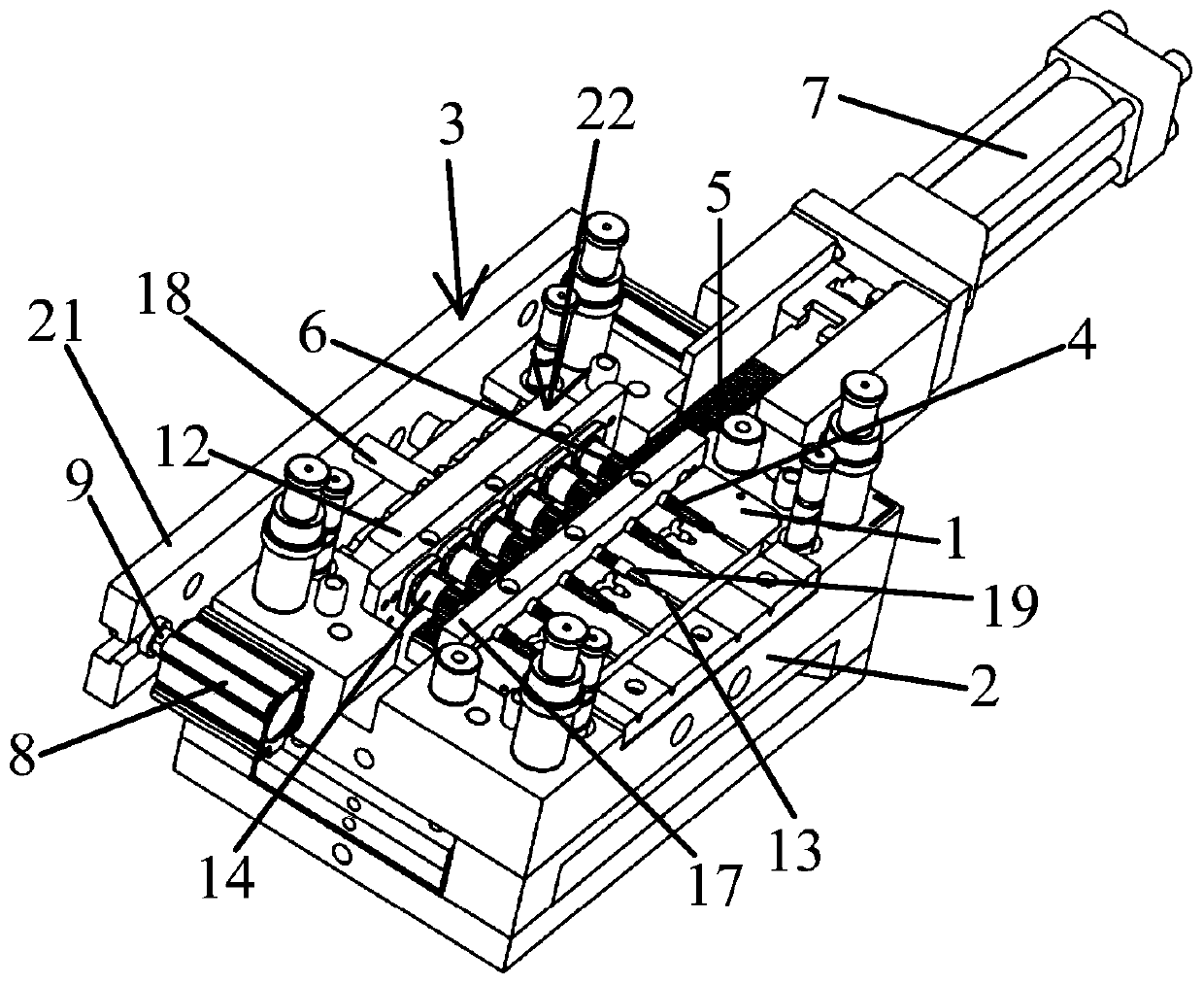
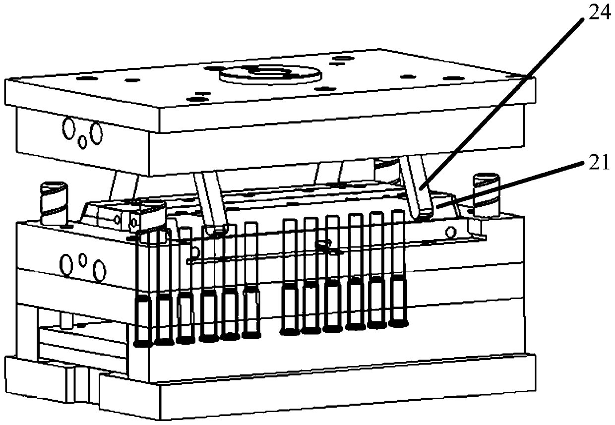
[0035] The injection mold such as figure 1 As shown, it includes: a cavity 1; a core 4, which is accommodated in the cavity 1 to form an injection molding cavity, and the core 4 has a mold clamping position close to the cavity 1 and a part far away from Die position; core-pulling structure 22, connected with the transmission of the core 4, to drive the core 4 to rotate along its circumferential direction, so as to switch between the mold clamping position and the mold splitting position. There are technologies such as image 3 As shown, the slider cavity is composed of a group of sliding movable blocks 21 arranged oppositely. The above-mentioned sliding movable blocks 21 are generally arranged on the lower mold. Moving up and down, during the movement, the square guide post 24 slides in the inclined slot, thereby pushing the sliding movable block 21 to move in the h...


PUM


Abstract

The invention provides an injection mold and an injection molding machine thereof. The injection mold comprises a cavity, a core and a core-pulling structure, and the core is arranged in the cavity toform an injection molding cavity; the core has a mold closing position close to the cavity, and a mold splitting position far away from the cavity; the core-pulling structure is in transmission connection with the core for driving the core to rotate in the circumferential direction of the core-pulling structure so as to switch between the mold closing position and the mold splitting position; andthrough supply of the injection mold, the problems that a square guide pillar 24 is slide in an inclined slot of a sliding block 21 and produces friction in the mold closing and splitting process ofan existing injection mold and an injection molding machine thereof, and consequently powder is generated and contaminates the products easily are solved.

Description

technical field [0001] The invention relates to the field of injection molds, in particular to an injection mold and an injection molding machine thereof. Background technique [0002] Injection mold is a tool for producing plastic products, and it is also a tool for giving plastic products a complete structure and precise dimensions. The plastic that is melted by heat is injected into the mold from the nozzle under high pressure, and after cooling and solidification, a molded product is obtained. [0003] At present, the slider cavity in the prior art is composed of a set of oppositely arranged sliding movable blocks. The above-mentioned sliding movable blocks are arranged on the lower mold. On the upper mold, during the mold clamping and parting process, the square guide column will move up and down in the vertical direction. During the movement, the square guide column will slide in the inclined slot of the sliding movable block, thereby pushing the sliding movable block ...

Claims


Application Information

Patent Timeline
Patent Type & Authority Applications(China)
IPC IPC(8): B29C45/33B29C45/26B29C45/44
CPCB29C45/332B29C45/26B29C45/44B29C2045/334B29C2045/2683
Inventor 不公告发明人
Owner 上海康德莱医疗器械自动化研究所有限公司
Why Eureka
Try Eureka