A rotatable clamping device for milling

A clamping device and milling technology, applied in the direction of positioning device, clamping, manufacturing tools, etc., can solve the problems of inconvenience, low work efficiency, loss of precision, etc., achieve comfortable processing, improve processing efficiency, and avoid re-alignment knife effect

Inactive Publication Date: 2020-10-30
东营昶晟精密铸造有限公司
View PDF7 Cites 0 Cited by
  • Summary
  • Abstract
  • Description
  • Claims
  • Application Information

AI Technical Summary

Problems solved by technology

When the workpiece is clamped, the workpiece cannot be clamped well, effectively, quickly, and evenly. During the clamping process, the surface of the workpiece needs to be protected for clamping. The processed surface should be taken good care of to avoid The accuracy is damaged; and when the workpiece clamping needs to change the direction during the milling process, the operator needs to manually change the direction, and after the direction change is completed, it is necessary to re-set the tool for the milled workpiece, which is very inconvenient and makes the work efficiency not high

Method used


Image

  • A rotatable clamping device for milling
  • A rotatable clamping device for milling
  • A rotatable clamping device for milling

Examples


Embodiment Construction

[0016] All features disclosed in this specification, or all disclosed methods or steps in the process, except for mutually exclusive features and / or steps, can be combined in any manner.

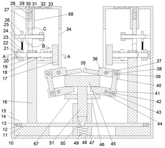
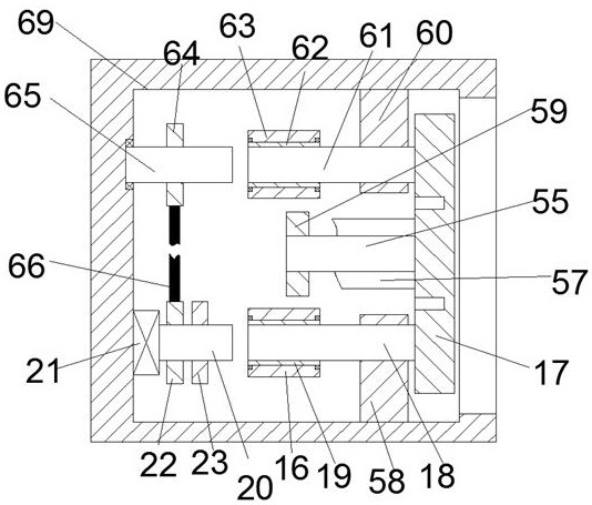
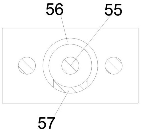
[0017] Combine below Figure 1-4 The present invention will be described in detail. For the convenience of description, the following directions are specified as follows: figure 1 The vertical, horizontal, front and rear directions of the projection relationship are the same.

[0018] A clamping device that can rotate during milling of the device of the present invention includes a mounting box 15 in which a mounting cavity 14 is provided, and the mounting cavity 14 is provided with a clamping platform and an effective support The load-bearing mechanism 67 on which the workpiece is stressed during the machining process. The load-bearing mechanism 67 includes a load-bearing box 47 fixedly installed on the bottom end wall of the mounting cavity 14. The load-bearing box 47 is provided with a load-be...


PUM


Abstract

The invention discloses a clamping device capable of rotating during milling. An installing box is included, and internally provided with an installing cavity; a bearing mechanism is arranged in the installing cavity, and comprises a bearing box fixedly installed at the bottom end wall of the installing cavity; a bearing cavity with an up-down opening is formed in the bearing box, and internally provided with an adjusting rod in a sliding manner; a trapezoidal block is fixedly installed on the lower end face of the adjusting rod; and front-rear symmetrical bearing springs are fixedly connectedbetween the lower end face of the trapezoidal block and the bottom end wall of the installing cavity. The surface of a workpiece can be effectively protected, and when rotating is needed, driving canbe achieved and automatic turning can be achieved, so that the workpiece can be turned without being disassembled and assembled again, the trouble caused when tool setting needs to be performed againis avoided, and people feel more comfortable in the machining process.

Description

Technical field [0001] The invention relates to the technical field related to milling, in particular to a clamping device that can rotate during milling. Background technique [0002] Milling refers to the use of rotating multi-edge tools to cut workpieces, and is a highly efficient processing method. When working, the tool rotates and the workpiece is fixedly installed, but the rotating tool must also move at the same time to complete the main movement and the feed movement. When the workpiece is clamped, the workpiece cannot be clamped very well, effectively, quickly, and with uniform force. During the clamping process, the surface of the workpiece needs to be protected for clamping, and the processed surface should be carefully taken care of. The accuracy is impaired; and when the workpiece clamping direction needs to be changed during the milling process, the operator needs to manually change the direction, and after the change is completed, the milled workpiece needs to be...

Claims


Application Information

Patent Timeline
Patent Type & Authority Patents(China)
IPC IPC(8): B23Q3/06B23Q7/00
CPCB23Q3/06B23Q7/00
Inventor 褚雅囡
Owner 东营昶晟精密铸造有限公司
Why Eureka
Try Eureka