


Quick Research
Generate reliable direction feasibility study reports for your R&D in just a few steps.

Technical Q&A
Discover and master advanced knowledge NOW. Basics, ideas, possibilities, all at once.

Find Solutions
As an expert in R&D theories, this can generate solutions to your technical problems instantly.

Evaluate Feasibility
Analyze your overall solution with one click, know your potential R&D risks in advance.

Monitor Landscape
Get weekly tech updates, stay abreast of the latest tech innovations and key insights.
A non-standard h-shaped steel assembly positioning fixture and positioning method
A technology for positioning fixtures and H-shaped steel, applied in the direction of manufacturing tools, auxiliary devices, metal processing equipment, etc., to achieve the effect of avoiding welding gaps, eliminating gaps, and reducing time waste
- Summary
- Abstract
- Description
- Claims
- Application Information
AI Technical Summary
Problems solved by technology
Method used
Image

Examples
Embodiment 1
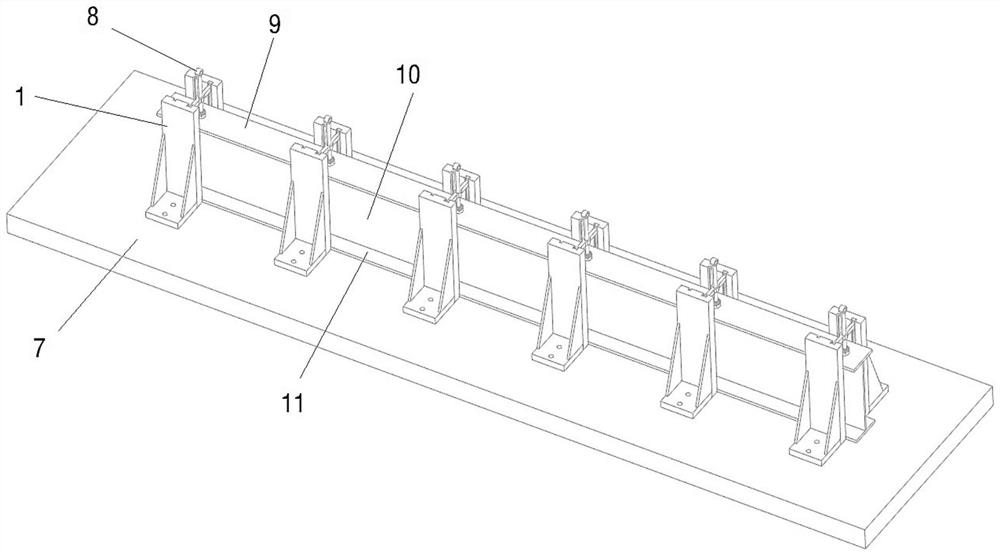
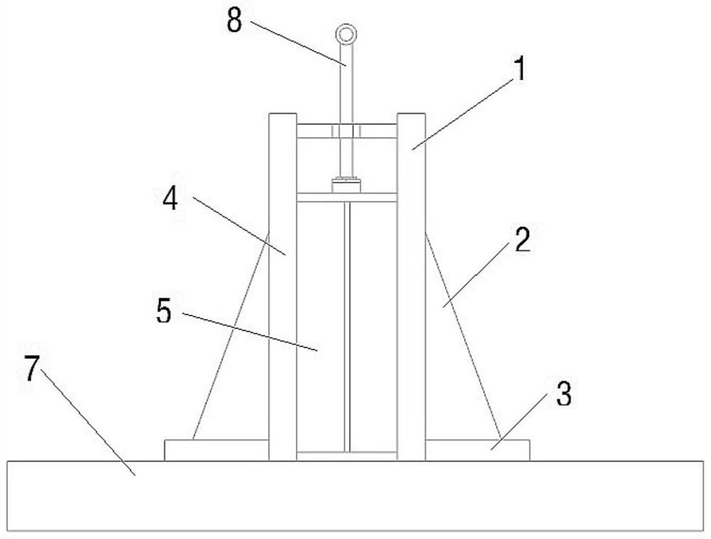
[0043] Such as Figure 1-7 As shown, a non-standard H-shaped steel assembly positioning fixture includes a platform 7, and the upper surface of the platform 7 is sequentially installed with a plurality of clamping assemblies along the set straight line direction, and each clamping assembly includes a first branch oppositely arranged. The seat 1 and the second support 4, the opposite sides of the first support 1 and the second support 4 are positioning surfaces, and the positioning surfaces are perpendicular to the upper surface of the platform 7 .
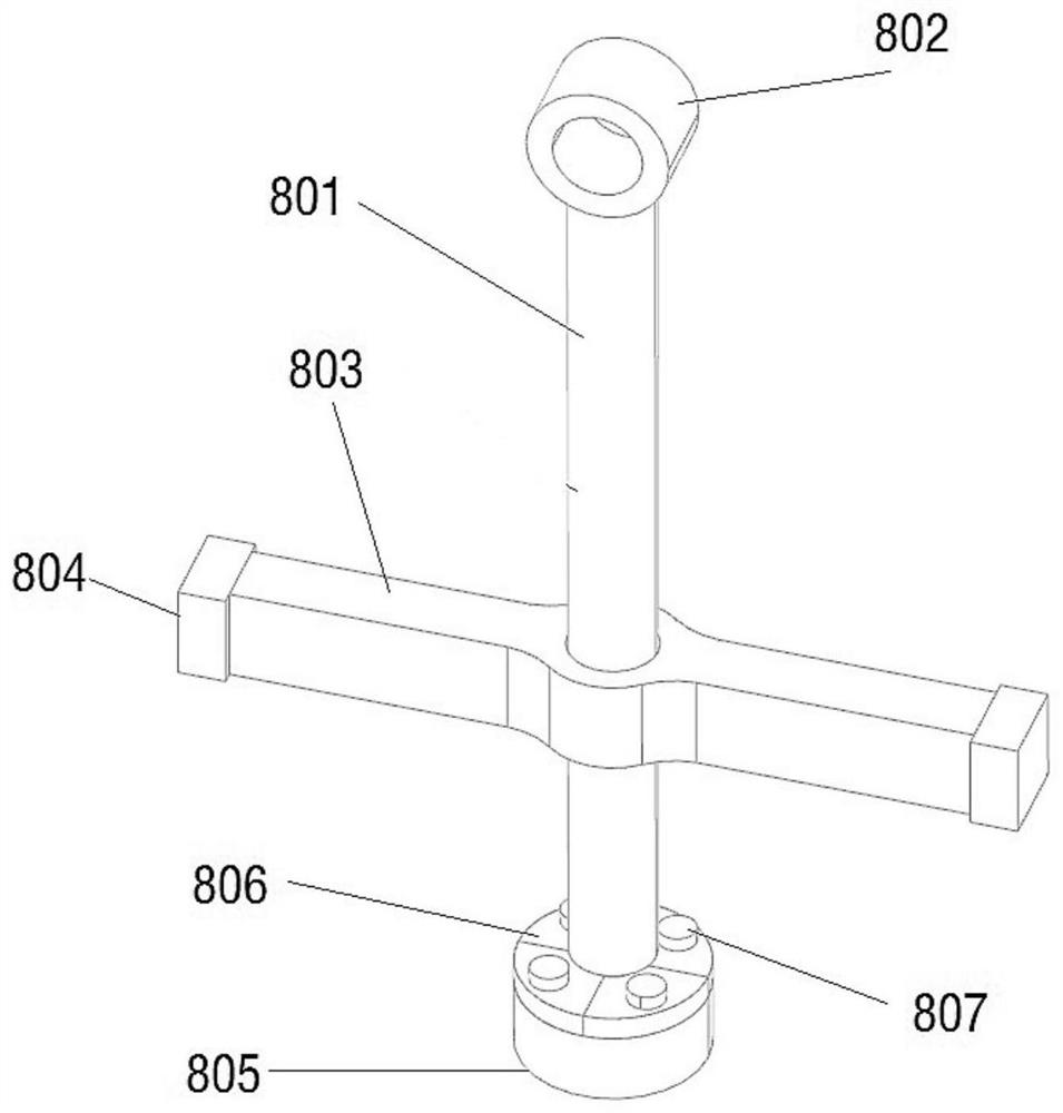
[0044] The positioning surface is provided with vertical chute 810, the upper end of the chute 810 runs through the upper end surface of the clamping assembly, and each chute 810 is provided with a positioning plate 5, and the extension of the positioning plate 5 and the clamping assembly The direction is vertical, there is a first setting gap between the two positioning plates 5 , and there is a second setting gap between the two ...
Embodiment 2
[0057] Such as Figure 8-12 As shown, this embodiment also provides a non-standard H-shaped steel assembly positioning method, which utilizes the non-standard H-shaped steel assembly positioning fixture, including the following steps,
[0058] Step 1, a row of second supports 4 is fixedly installed on the platform 7, and the positioning surfaces of multiple second supports 4 are on the same plane;
[0059] Step 2, placing the lower wing plate 11 of the H-shaped steel to be assembled on the upper surface of the platform 7, and the side of the lower wing plate 11 is attached to the positioning surface of the second support 4;
[0060] Step 3, fixedly install a row of first supports 1 on the platform 7, so that the positioning surface of the first supports 1 fits with the other side of the lower wing plate 11;
[0061] Step 4, install the positioning plate 5 in the chute 810, and insert one vertical side of the positioning plate into the chute, so that the positioning plate is p...
PUM
 Abstract
Description
Claims
Application Information
 - R&D Engineer
- R&D Manager
- IP Professional
- Industry Leading Data Capabilities
- Powerful AI technology
- Patent DNA Extraction
Browse by: Latest US Patents, China's latest patents, Technical Efficacy Thesaurus, Application Domain, Technology Topic, Popular Technical Reports.
© 2024 PatSnap. All rights reserved.Legal|Privacy policy|Modern Slavery Act Transparency Statement|Sitemap|About US| Contact US: help@patsnap.com