Mold releasing device
A demoulding device and mold technology, applied in the field of molds, can solve problems such as large installation area, difficult demoulding, product damage, etc., to achieve the effect of protecting the mold, convenient and quick demoulding, and preventing damage
Inactive Publication Date: 2020-06-09
重庆奥阳模具制造有限公司
View PDF0 Cites 2 Cited by
- Summary
- Abstract
- Description
- Claims
- Application Information
AI Technical Summary
Problems solved by technology
Due to the need to install the oil cylinder, the space of the casting machine table is relatively large, the installation area is large, and the operating space of the casting site is also limited. In the prior art
[0003] After the traditional mold is processed and shaped, it is difficult to demould. If you are not careful, the product will be damaged. Therefore, it is necessary to invent a mold demoulding device
Method used
View moreImage
Smart ImageViewing Examples

Examples
Embodiment approach
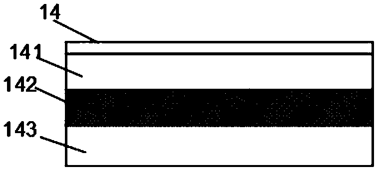
[0021] As a preferred embodiment of the present invention, the top membrane device 14 includes a push plate 141 , a sealing layer 142 and a gasket 143 , and the sealing layer 142 is placed between the push plate 141 and the gasket 143 .
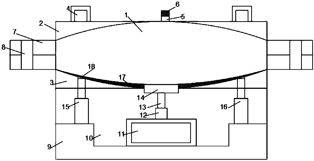
[0022] As a preferred embodiment of the present invention, a release layer 17 is fixedly installed on the inner wall of the lower mold 3 .
Login to View More PUM
 Abstract
The invention discloses a mold releasing device. The device comprises an upper mold and a lower mold, the upper mold and the lower mold jointly form a mold cavity, an injection molding opening is fixedly formed in the middle of the upper mold, a seal cover is fixedly mounted on the injection molding opening, through the upper mold and the lower mold, a product mold can be casted, through a drivingmotor and a mold ejecting device, mold taking can be facilitated, a thread screw is used for ejecting the mold, a left telescopic rod and a right telescopic rod are mounted to stably take out the mold, damage is prevented, through the injection molding opening, the mold can be achieved, a mold releasing layer is mounted, mold releasing is more convenient and rapid, and an anti-collision layer ismounted, in the mold taking process, the mold is protected.
Description
technical field [0001] The invention relates to the technical field of molds, in particular to a mold demoulding device. Background technique [0002] When casting barrel-shaped parts with complex side shapes such as automobile hubs, the molds used generally include upper and lower molds arranged above and below, and side molds arranged on the periphery of the upper and lower molds. Since the casting is relatively large, the mold used for casting is very large and heavy, and the pressure required for casting is involved. Generally, the structure of the mold similar to the automobile wheel hub casting is relatively complicated, and in order to be able to drive the side mold and the upper mold Or the movement of the lower mold to complete the opening and closing action of the mold such as the side mold, and a drive cylinder for driving the side mold to move outward is also specially arranged on the left and right spaces of each of the side molds. Due to the need to install th...
Claims
Login to View More Application Information
Patent Timeline
 Patent Type & Authority Applications(China)
IPC IPC(8): B22D17/26
CPCB22D17/263
Inventor 曾素容
Owner 重庆奥阳模具制造有限公司
Features
- R&D
- Intellectual Property
- Life Sciences
- Materials
- Tech Scout
- Unparalleled Data Quality
- Higher Quality Content
- 60% Fewer Hallucinations
Learn More Browse by: Latest US Patents, China's latest patents, Technical Efficacy Thesaurus, Application Domain, Technology Topic, Popular Technical Reports.
© 2025 PatSnap. All rights reserved.Legal|Privacy policy|Modern Slavery Act Transparency Statement|Sitemap|About US| Contact US: help@patsnap.com