


Quick Research
Generate reliable direction feasibility study reports for your R&D in just a few steps.

Technical Q&A
Discover and master advanced knowledge NOW. Basics, ideas, possibilities, all at once.

Find Solutions
As an expert in R&D theories, this can generate solutions to your technical problems instantly.

Evaluate Feasibility
Analyze your overall solution with one click, know your potential R&D risks in advance.

Monitor Landscape
Get weekly tech updates, stay abreast of the latest tech innovations and key insights.
Shoe wearing and taking-off mechanism and automatic shoe wearing and taking-off device
An automatic putting on and taking off technology, which is applied in clothing, applications, hangers, etc., can solve the problems of being unable to bend over to put on and take off shoes, and the structure of the automatic putting on and taking off shoes is complicated, and achieves the effect of simple structure
- Summary
- Abstract
- Description
- Claims
- Application Information
AI Technical Summary
Problems solved by technology
Method used
Image

Examples
Embodiment 1
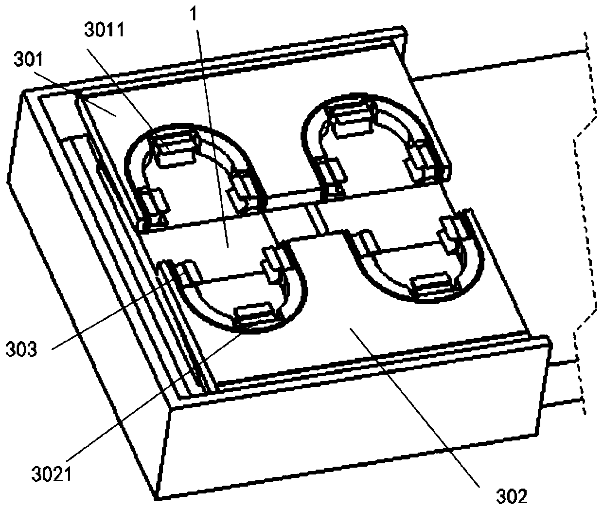
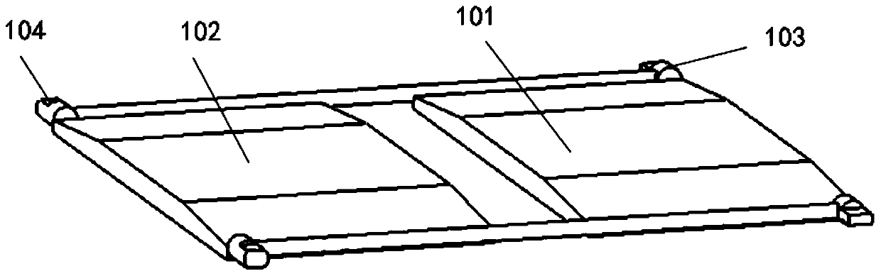
[0029] Such as figure 1 As shown, the present embodiment provides a mechanism for putting on and taking off shoes, which includes two shoe taking off boards 1 arranged horizontally. The two shoe taking off boards 1 can respectively support the user's two soles. There are protrusions, so that when the sole of the foot is supported by the shoe board 1, the sole of the foot and the front and rear ends of the shoe 7 are bent downward by gravity;
[0030] A clamping assembly 2 is arranged above the shoe removal board 1, and the clamping assembly 2 is supported by a supporting assembly 10, and the clamping assembly 2 can realize the clamping and loosening of the front and rear ends of the shoe 7;
[0031] The bending of the front and rear ends of the shoe 7 relative to the middle part can increase the size of the opening of the shoe 7 so as to complete the putting on and taking off of the sole of the foot from the opening of the shoe 7 .
[0032] Shoe removal board 1: the middle pa...
Embodiment 2
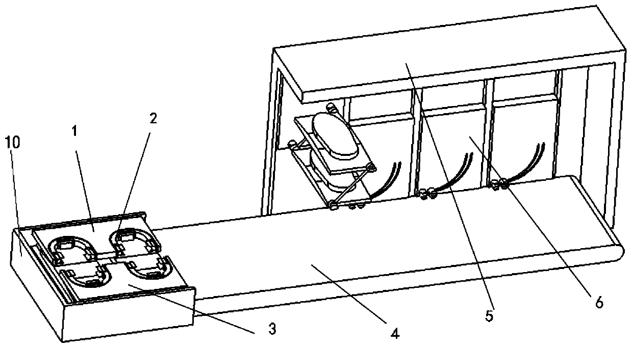
[0049] Such as Figure 1-5 As shown, the present embodiment provides an automatic shoe-wearing and taking-off device, which includes the shoe-wearing and taking-off mechanism described in Embodiment 1, and also includes a conveyor belt 4 that can reciprocate along a set direction, and one end of the conveyor belt 4 is provided with a As for the shoe-wearing and taking-off mechanism, the other end is provided with a plurality of shoe-hanging mechanisms, and the shoe-hanging mechanism can realize the lifting and storage of the shoe-removing board 1 and the shoes 7; It reciprocates between the putting on and taking off shoes mechanism and the shoe hanging mechanism.
[0050] In this embodiment, two shoe-removing boards 1 are used in groups, and multiple groups of shoe-removing boards 1 can be stored in the shoe-hanging mechanism to complete the suspension and storage of multiple pairs of shoes 7 .
[0051] It should be understood that, under the condition that multiple pairs of ...
PUM
 Abstract
Description
Claims
Application Information
 - R&D Engineer
- R&D Manager
- IP Professional
- Industry Leading Data Capabilities
- Powerful AI technology
- Patent DNA Extraction
Browse by: Latest US Patents, China's latest patents, Technical Efficacy Thesaurus, Application Domain, Technology Topic, Popular Technical Reports.
© 2024 PatSnap. All rights reserved.Legal|Privacy policy|Modern Slavery Act Transparency Statement|Sitemap|About US| Contact US: help@patsnap.com