
Detection Method of Resonant Optical Gyroscope Based on Reciprocity Modulation and Time Division Switching

An optical gyroscope and detection method technology, applied in the field of signal detection, to achieve the effects of suppressing spurious intensity modulation, realizing backscattering intensity noise and partial interference term noise, and improving reciprocity

Active Publication Date: 2021-11-09
ZHEJIANG UNIV
View PDF10 Cites 0 Cited by
  • Summary
  • Abstract
  • Description
  • Claims
  • Application Information

AI Technical Summary

Problems solved by technology

Laser phase modulation is generally realized by integrated optical phase modulation such as lithium niobate. Research has found that the non-ideal phase modulation characteristics of the phase modulator means that when a voltage signal is applied to the phase modulator for phase modulation, it is often accompanied by spurious intensity modulation. , the spurious intensity modulation and phase modulation signals have the same frequency characteristics, and will be demodulated by the signal demodulation module at the output end of the resonator. The influence of the spurious intensity modulation in the opposite direction is also different, and the residual intensity modulation eventually becomes a constraint on the detection accuracy of the resonant optical gyroscope.

Method used


Image

  • Detection Method of Resonant Optical Gyroscope Based on Reciprocity Modulation and Time Division Switching
  • Detection Method of Resonant Optical Gyroscope Based on Reciprocity Modulation and Time Division Switching
  • Detection Method of Resonant Optical Gyroscope Based on Reciprocity Modulation and Time Division Switching

Examples


Embodiment Construction

[0027] The present invention will be described in detail below in conjunction with the embodiments and accompanying drawings, but the present invention is not limited thereto.

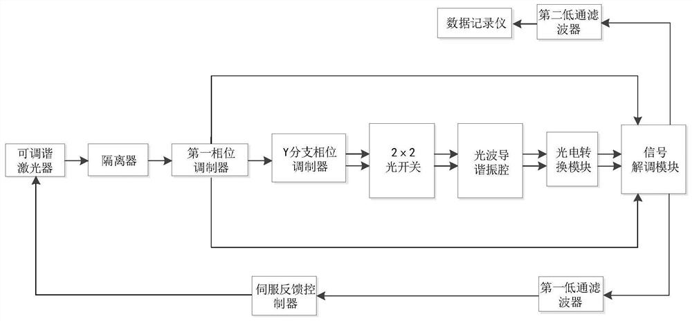
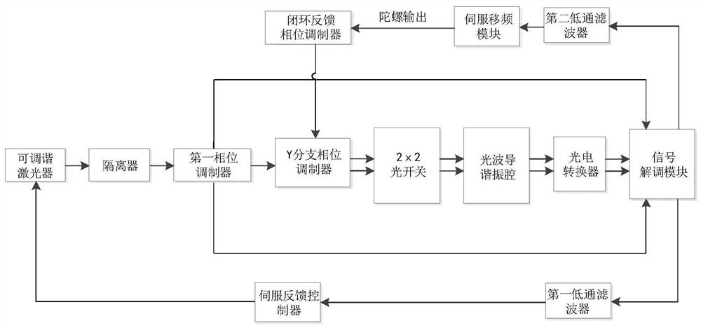
[0028] Such as figure 1As shown, a resonant optical gyro detection system based on the combination of reciprocal phase modulation and time-division switching is mainly composed of tunable laser, optical isolator, first phase modulator, Y branch, optical resonant cavity, photoelectric An optical system composed of a conversion module and a signal processing system composed of a signal modulation and demodulation module, a feedback locking module, a first signal processing module, a second signal processing module, a servo frequency shifting module, and a closed-loop feedback phase modulator. The tunable laser, the optical isolator, the phase modulator and the Y branch are connected in sequence, and the two outputs of the Y branch are respectively connected to the two inputs of the 2×2 optical switch, an...


PUM


Abstract

The invention discloses a resonant optical gyro detection system and method based on the combination of reciprocity modulation and time-division switching. First, reciprocity modulation is performed on the light emitted by the laser, and then two paths of light are obtained in the Y branch in the clockwise and counterclockwise directions (relative to the propagation direction along the optical resonator), and at the same time, different frequency modulation signals are applied to modulate the two beams of light; the Y branch The output enters the 2×2 optical switch for time-division switching, and its output enters the optical resonant cavity. The out-of-cavity signal is demodulated at the same frequency, and one of the demodulated signals is fed back to the laser tuning end after signal processing, so that the laser frequency is locked on the resonance frequency of the channel. The other demodulated signal is output as the gyro rotation signal after signal processing. The resonant optical gyroscope detection method provided by the invention is beneficial to suppress the influence of non-reciprocal noise such as residual intensity modulation on the basis of increasing the system carrier rejection ratio and suppressing backscattering noise, and improve the detection accuracy of the resonant optical gyroscope .

Description

technical field [0001] The invention relates to the technical field of signal detection, and relates to a detection system and method for a resonant optical gyroscope based on the combination of reciprocity modulation and time-division switching of 2×2 optical switches. Resonant gyroscopes include resonant fiber optic gyroscopes with optical fiber ring resonators as sensitive components and resonant integrated optical gyroscopes with optical resonant cavities as core sensitive components. Background technique [0002] Resonator Optic Gyroscope (ROG) is a high-precision inertial sensor that uses the optical Sagnac effect to detect rotation. The resonant optical gyroscope without vibrating parts has the advantages of miniaturization, high precision and anti-vibration. Compared with Micro Electro Mechanical Systems (MEMS) and Interferometric Fiber Optical Gyroscope (IFOG), ROG will have greater advantages. [0003] Since the Sagnac effect is a very weak effect, and the optica...

Claims


Application Information

Patent Timeline
Patent Type & Authority Patents(China)
IPC IPC(8): G01C19/72G02B6/27G02B6/35
CPCG01C19/72G01C19/721G02B6/2746G02B6/3546
Inventor 钱伟文吴传斌马慧莲
Owner ZHEJIANG UNIV
Learn More