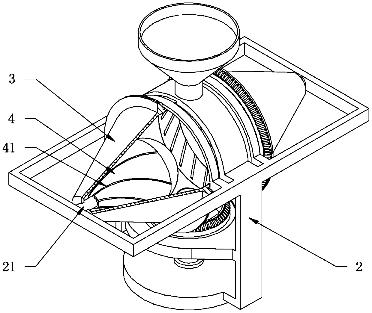
Graded twisting machine for tea leaves
A graded, kneading machine technology, applied in tea processing before extraction, etc., can solve problems such as uneven rolling, poor stability, and non-adjustable rolling strength and speed, and achieve adjustable rolling strength, adjustable rolling speed, and stability Good results
- Summary
- Abstract
- Description
- Claims
- Application Information
AI Technical Summary
Problems solved by technology
Method used
Image
Examples
Embodiment 1
[0038] see Figure 1-4, a tea graded rolling machine, comprising a bearing plate 1, a bearing frame 2 horizontally rotated on the bearing plate 1, two conical sleeves 3 located in the bearing frame 2 with concentric centers and axes distributed horizontally, located in the conical The cone 4 in the sleeve 3, wherein the bearing plate 1 acts as a base, and the bearing frame 2 can adopt the structure shown in the figure to mainly support the cone sleeve 3 and the cone 4. The cone sleeve 3 is used to hold the tea leaves that need to be rolled. The body 4 is used as a resistance part for tea rolling; the large ends of the two conical sleeves 3 are opposite and distributed symmetrically with respect to the center of rotation of the carrier 2, and the inner wall of the carrier 2 is fixedly provided with a small end passing through the conical sleeve 3 and connected to the cone. The small end of the body 4 is elastic and axially slidingly fitted with the support shaft 21, and the con...
Embodiment 2
[0040] see Figure 5-8 The difference from Example 1 is that the top of the transition sleeve 22 is fixedly connected with a feed funnel 221 and the bottom is provided with a discharge port 222, and the centers of rotation of the feed funnel 221, discharge port 222 and transition sleeve 22 are coaxially distributed. , the feeding funnel 221 is used for feeding the tea leaves, and the discharge port 222 is used for discharging the rolled tea leaves. The discharge port 222 and the feeding funnel 221 are located at the center of the rotation, with good dynamic stability and convenient loading and unloading operations; The middle part of the bevel gear 5 is provided with a relief hole 51 corresponding to the discharge port 222, and the electric telescopic rod 6 is fixedly installed on the carrier frame 2 and positioned at the bottom of the transmission bevel gear 5, and the top of the electric telescopic rod 6 is fixedly provided with and let The sealing disc 61 of the position ho...
Embodiment 3
[0042] see Figure 7 Based on the further description of Embodiment 1, the drive disc 8 is fixedly arranged on the outer periphery of the transmission bevel gear 5 in the carrier 2, and the outer periphery of the transmission bevel gear 5 is fixedly provided with an annular disc 52, and the drive disc 8 includes an annular disc 52 52, the disk sleeve 81 that rotates in the outer periphery, the drive gear 82 that is located in the disk sleeve 81 and the outer mesh of the annular disk 52, and the speed-regulating motor 83 that is fixedly arranged at the bottom of the disk sleeve 81 and is fixedly connected with the drive gear 82, the speed-regulating motor One 83 drives the driving gear 82 to rotate, and the driving gear 82 drives the transmission bevel gear 5 to rotate through the inner core of the annular disc 52, and drives the two conical sleeves 3 to rotate; for realizing the beneficial effect produced by embodiment 1, the transmission bevel gear 5 is driven to rotate The d...
PUM
 Abstract
Description
Claims
Application Information
 - Generate Ideas
- Intellectual Property
- Life Sciences
- Materials
- Tech Scout
- Unparalleled Data Quality
- Higher Quality Content
- 60% Fewer Hallucinations
Browse by: Latest US Patents, China's latest patents, Technical Efficacy Thesaurus, Application Domain, Technology Topic, Popular Technical Reports.
© 2025 PatSnap. All rights reserved.Legal|Privacy policy|Modern Slavery Act Transparency Statement|Sitemap|About US| Contact US: help@patsnap.com


