Probability demonstration device
A demonstration device and probability technology, applied in the field of teaching, can solve the problems of sore arms and hands, complicated operation, troublesome and other problems, and achieve the effect of reducing work intensity and facilitating statistics.
- Summary
- Abstract
- Description
- Claims
- Application Information
AI Technical Summary
Problems solved by technology
Method used
Image
Examples
Embodiment 1
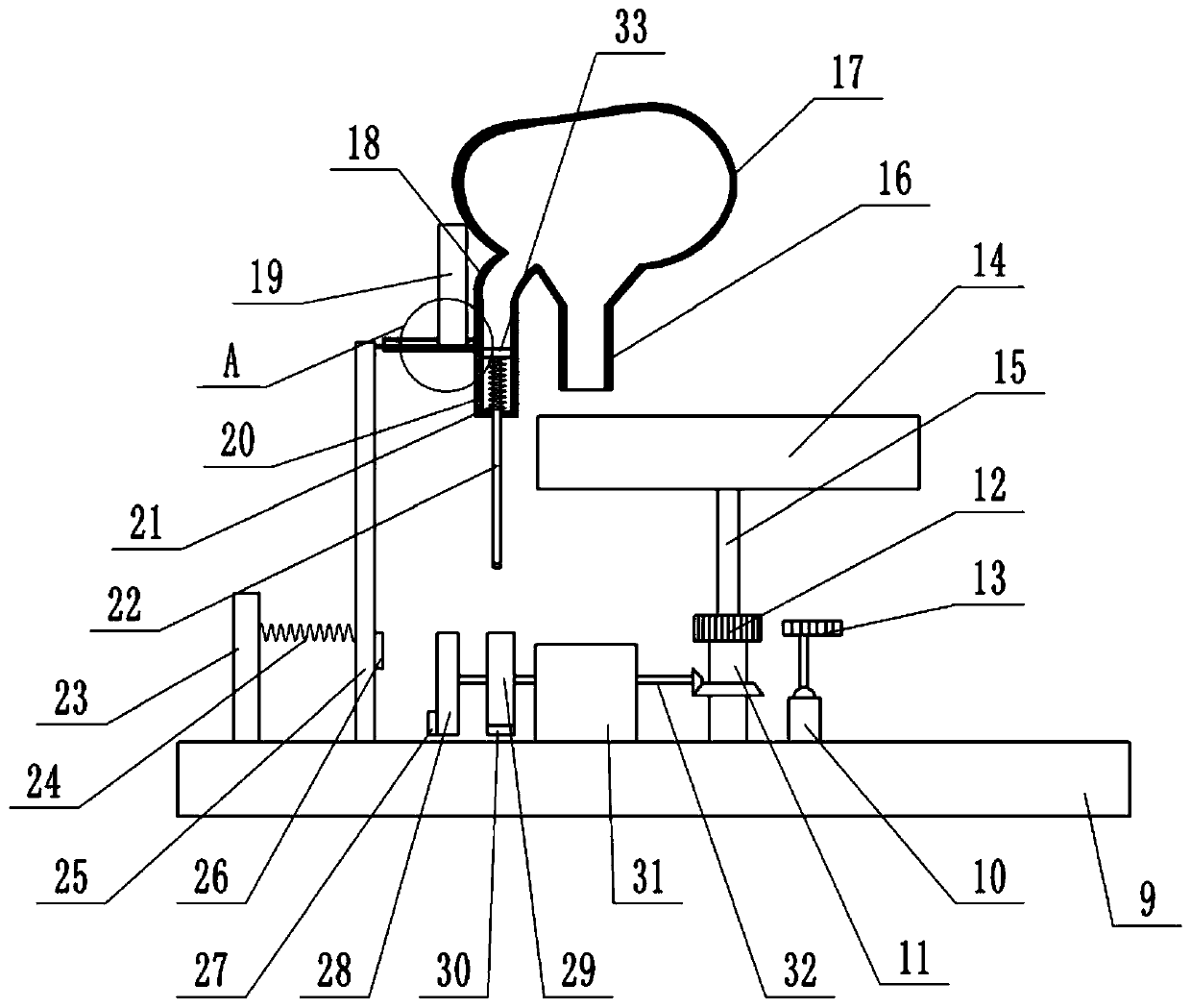
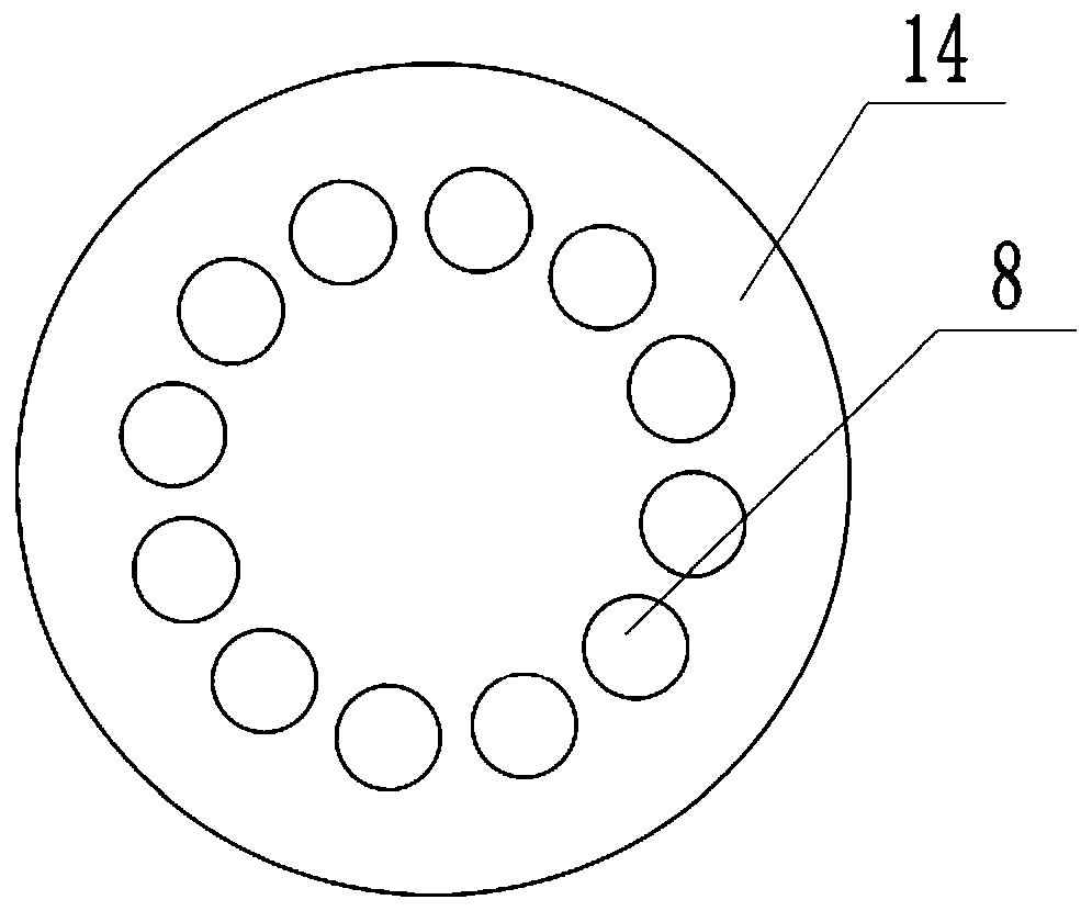
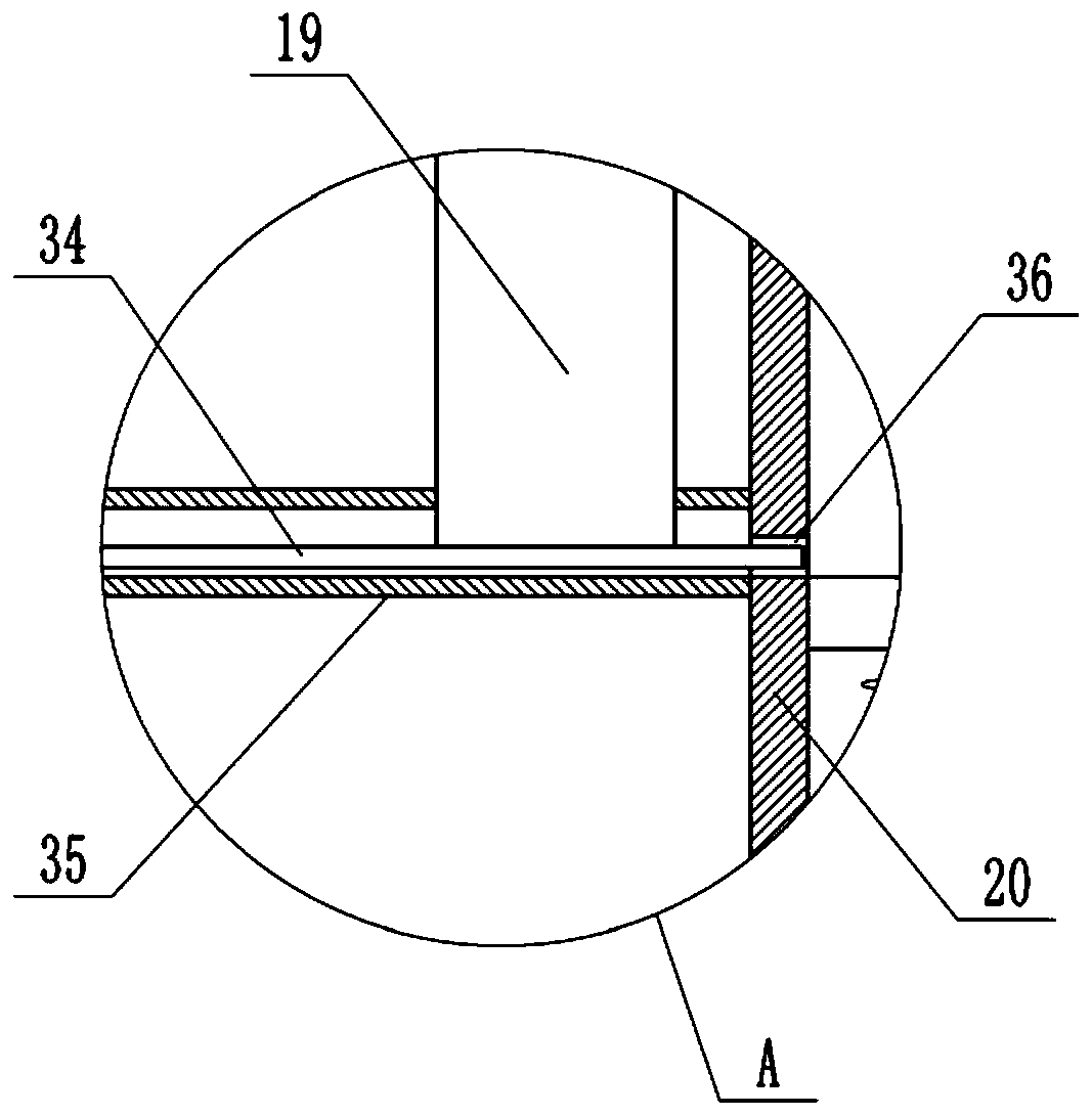
[0026] Basic as attached Figure 1-Figure 3Shown: a probability demonstration device, including a base 9, a coin storage unit, a coin-operating unit and a coin-receiving unit, the coin-operating unit includes a launching cylinder 20, an inversion cavity 17 and a discharging cylinder 16, the launching cylinder 20, and the discharging cylinder 16 It is welded together with the turning cavity 17, and a supporting frame (not shown in the figure) is connected between the coin-operating unit and the base 9, thereby supporting the coin-operating unit. The launching tube 20 and the discharging tube 16 are all communicated with the turning cavity 17, the launching tube 20 is positioned at the left side of the discharging tube 16, the launching tube 20 and the discharging tube 16 are all vertically arranged, the welding between the launching tube 20 and the turning cavity 17 There is an arc-shaped cylinder 18, and the launching cylinder 20 and the discharging cylinder 16 are all located...
Embodiment 2
[0036] combine Figure 4 As shown, in this embodiment, the top of the connection between the arc-shaped cylinder 18 and the turning chamber 17 is connected with an inclined cover plate 37 through a pin shaft rotation.
[0037] Thus, when the coin comes out of the arc tube 18, the coin impacts the cover plate 37, thereby pushing the cover plate 37 away, and the cover plate 37 will not block the coin from coming out of the arc tube 18. When the coin leaves the arc tube 18, the cover plate 37 will automatically cover the top of the arc tube 18 under the action of its own gravity, thereby preventing the coins entering the turning chamber 17 from entering the arc tube 18 by mistake, and the energy can be 100%. It is guaranteed that the coin enters the discharge cylinder 16 from the turning cavity 17, and compared with Embodiment 1, the possibility of the coin returning to the arc-shaped cylinder 18 is further avoided. In addition, since the cover plate 37 is inclined, even if the ...
Embodiment 3
[0040] combine Figure 5 and Figure 6 As shown, in this embodiment, another structure of the rotating disk 14 is improved. The rotating disk 14 includes a receiving part 5 and a collecting part 4 located below the receiving part 5. The receiving part 5 communicates with the collecting part 4, and the receiving part 5 and the collecting part Part 4 is provided with a chamber for containing coins, and the middle part of the rotating disk 14 is welded with a fixed shaft 7, and a number of movable leaves 6 are rotationally connected between the fixed shaft 7 and the inner wall of the receiving part 5. Specifically, the movable leaves 6 are fan-shaped , the small end of the movable leaf 6 is connected with the fixed shaft 7 by pin rotation, the large end of the movable leaf 6 is connected with the receiving part 5 by the pin shaft, and the two sides of the movable leaf 6 are provided with coin receiving grooves 8, The pin shafts on the big ends of the two adjacent movable leaves ...
PUM
 Abstract
Description
Claims
Application Information
 - R&D
- Intellectual Property
- Life Sciences
- Materials
- Tech Scout
- Unparalleled Data Quality
- Higher Quality Content
- 60% Fewer Hallucinations
Browse by: Latest US Patents, China's latest patents, Technical Efficacy Thesaurus, Application Domain, Technology Topic, Popular Technical Reports.
© 2025 PatSnap. All rights reserved.Legal|Privacy policy|Modern Slavery Act Transparency Statement|Sitemap|About US| Contact US: help@patsnap.com


