
High-capacity lithium battery with high-energy-density multi-pole column structure

A technology with high energy density and column structure, which is applied to structural parts, secondary batteries, battery pack parts, etc., can solve the problems of long total length of lithium batteries and occupying more space, so as to save production time and improve production efficiency , cost-saving effect

Active Publication Date: 2020-05-29
东方醒狮新动力电池有限公司
View PDF8 Cites 2 Cited by
  • Summary
  • Abstract
  • Description
  • Claims
  • Application Information

AI Technical Summary

Problems solved by technology

[0006] The above-mentioned existing technical solutions have the following defects: because lithium batteries generate heat during operation, when multiple lithium batteries are used together, any adjacent two lithium batteries need to be separated to ensure ventilation. For the above reasons , multiple lithium batteries cannot be put together in a stacked manner when in use, therefore, multiple lithium batteries are generally erected when in use, and the poles of the lithium battery are respectively drawn from the two symmetrical sides of the shell , resulting in a longer total length of the lithium battery, which requires more space when the lithium battery is placed side by side, so it needs to be improved

Method used


Image

  • High-capacity lithium battery with high-energy-density multi-pole column structure
  • High-capacity lithium battery with high-energy-density multi-pole column structure
  • High-capacity lithium battery with high-energy-density multi-pole column structure

Examples


Embodiment 2

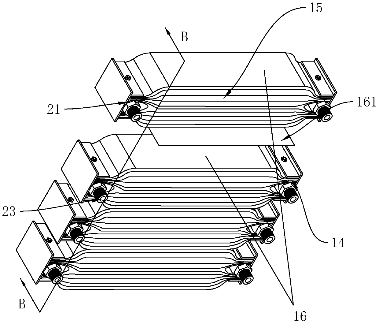
[0057] combine image 3 with Figure 4 As shown, the difference from Embodiment 1 is that the battery core 1 is formed by a combination of several sub-cores 15, and the bundle head 2 with a pole is provided with several pieces and evenly distributed at both ends of each sub-core 15, and the The bundle head 2 with a pole at one end of the sub-core body 15 is connected to the uncoated base half surface end 14 of each positive electrode piece 11 of the sub-core body 15, and the bundle head 2 with a pole set at the other end of the sub-core body 15 It is connected to the uncoated base half surface end 14 of each negative electrode sheet 12 of the sub-core body 15; wherein, on one of the side surfaces of each sub-core body 15, two battery core bodies for any adjacent arrangement are pasted 1 separated second diaphragm 16 , and a release film 161 is pasted on the side of each second diaphragm 16 away from the sub-core body 15 .

[0058] When it is necessary to connect any adjacent...

Embodiment 3

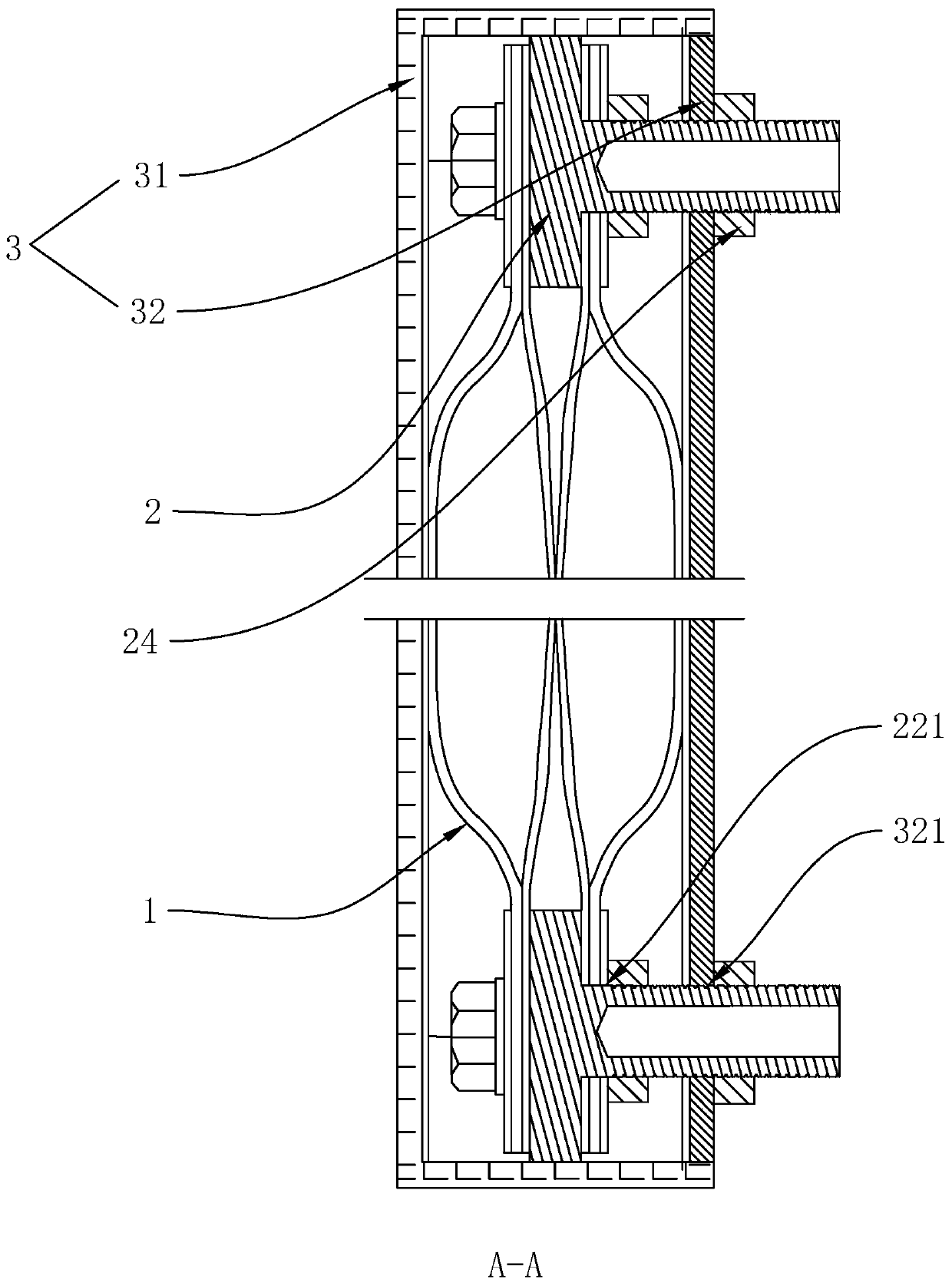
[0062] combine Figure 5 with Image 6 As shown, the difference from Embodiment 1 is that the battery core 1 is formed by combining several sub-cores 15 , and the casing 3 includes a battery case 31 with a side opening and a cover plate 32 for covering the opening of the battery case 31 A plurality of through holes 321 arranged along the width direction of the cover plate 32 are provided on both ends of the cover plate 32 and on both ends of the side of the battery case 31 away from the opening, and the holes 321 arranged on the cover plate 32 The positions of the through holes 321 and the through holes 321 disposed on the battery case 31 are alternately arranged.

[0063] When it is necessary to assemble each sub-core body 15 with the housing 3, at first one of the sub-core bodies 15 is installed on one side of the battery case 31, and the width direction of the sub-core body 15 is along the along the thickness direction of the battery case 31, and make the length direction...

Embodiment 4

[0066] combine Figure 7 with Figure 8 As shown, the difference from Embodiment 1 is that the casing 3 includes a battery case 31 with a side opening and a cover plate 32 for covering the opening of the battery case 31. On both ends of the cover plate 32 and the battery case 31 is away from Both ends of one side of the opening are provided with a plurality of through holes 321 arranged along the width direction of the cover plate 32 , and the through holes 321 arranged on the cover plate 32 are connected with the through holes 321 arranged on the battery case 31 . The through holes 321 are arranged as mirror images of each other; wherein, there are two poles 23 on the beam head body 21 , and the two poles 23 are symmetrically arranged on the left and right sides of the beam head body 21 .

[0067] When it is necessary to assemble each sub-core body 15 with the housing 3, it is only necessary to put each sub-core body 15 into the housing 3 from the opening of the battery case...


PUM


Abstract

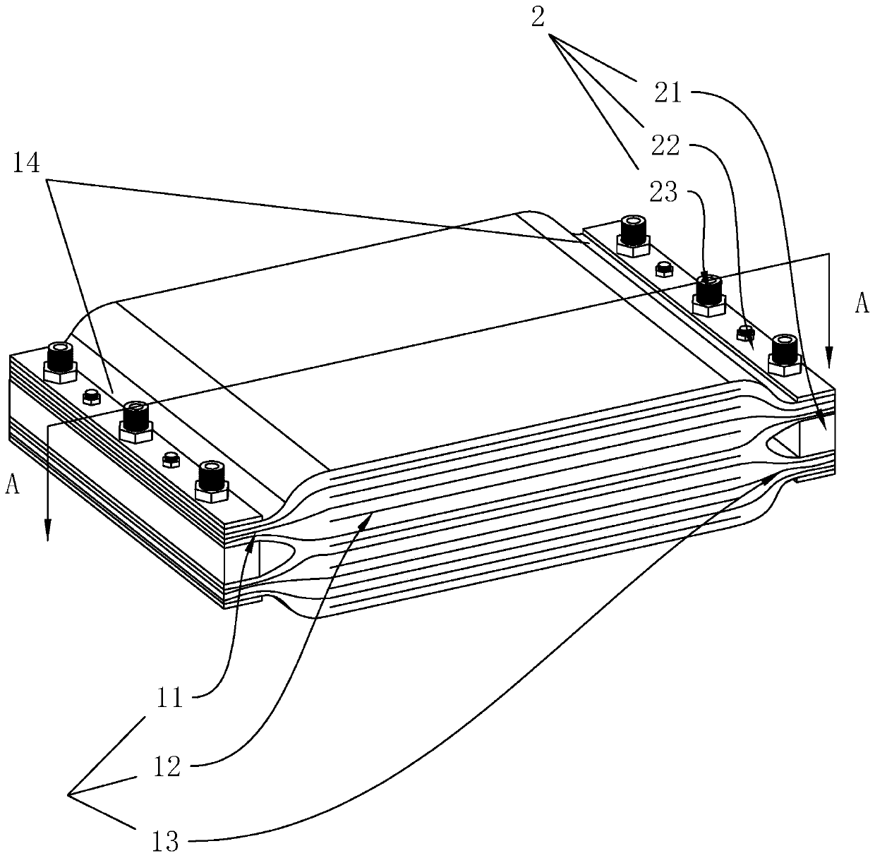
The invention relates to a high-capacity lithium battery with a high-energy-density multi-pole column structure and relates to the technical field of lithium batteries. The lithium battery comprises ashell filled with an electrolyte and a battery core body arranged in the shell, wherein the battery core body is formed by alternately stacking more than two rectangular sheet-shaped positive plates,negative plates and a plurality of first diaphragms; coating-free base half surface ends of the positive plates and the negative plates of the battery core body are arranged in opposite directions; each positive plate and each negative plate of the battery core body are bound through beamheads with polecolumns; and the shell includes a battery shell with an opening in one side and a cover plate for covering the opening of the battery shell, a plurality of through holes are arranged in the shell, and axes of the polecolumns ofthe beam heads with polecolumns are arranged in a thickness direction of the shell and extend out of the shell through the through holes respectively. By using the novel lithium battery, when a high-energy density material is provided, an occupied space is small, andan effect of bearing high-current input and output can be achieved.

Description

technical field [0001] The invention relates to the technical field of lithium batteries, in particular to a high-energy-density multi-pole structure and large-capacity lithium battery. Background technique [0002] Lithium batteries, also known as lithium-ion batteries, at present, in order to increase the storage capacity of lithium batteries to prolong the discharge time of lithium batteries, manufacturers have proposed many technical solutions that can increase the capacity of lithium batteries, such as Chinese patent CN1307376A "A Reusable Chromium fluoride lithium solid power battery for charge and discharge", CN2615878Y "Repeatable charge and discharge high-capacity power lithium battery with structural improvement", CN2615877Y "Repeatable charge and discharge high-voltage lithium-ion battery", etc., provide a great support for the manufacture of large-capacity lithium batteries As a practical technical solution, it can be seen from the published patent documents that...

Claims


Application Information

Patent Timeline
IPC IPC(8): H01M2/30H01M10/058H01M10/0525H01M10/613H01M10/6562
CPCH01M10/058H01M10/0525H01M10/613H01M10/6562H01M50/543Y02E60/10Y02P70/50
Inventor 钟旭航
Owner 东方醒狮新动力电池有限公司
Learn More