
Pixel driving circuit, display device and pixel driving method

A pixel driving circuit and circuit technology, applied in static indicators, instruments, etc., can solve the problems of data signal lines of data signals that cannot be written, complicated operations, etc., to reduce pixel spacing, avoid complex operations, and improve pixel charging speed. Effect

Active Publication Date: 2022-07-29
BOE TECH GRP CO LTD
View PDF6 Cites 0 Cited by
  • Summary
  • Abstract
  • Description
  • Claims
  • Application Information

AI Technical Summary

Problems solved by technology

[0004] In view of the shortcomings of the existing methods, this application proposes a pixel driving circuit, a display device and a pixel driving method, which can solve the problem that the data signal of the data signal line in the prior art cannot be written into the phase-locked loop, and timing optimization is required. Come operationally complex technical issues

Method used


Image

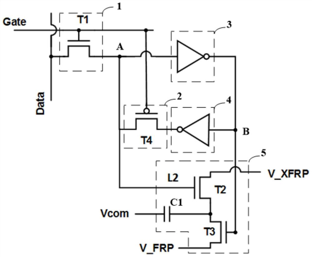
  • Pixel driving circuit, display device and pixel driving method
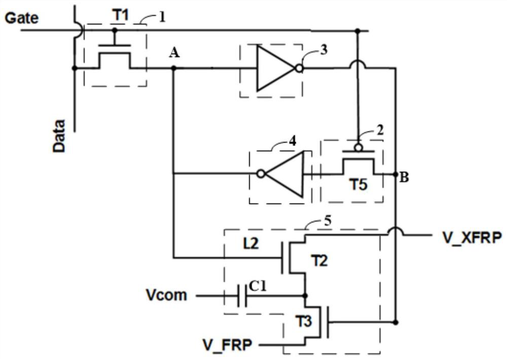
  • Pixel driving circuit, display device and pixel driving method
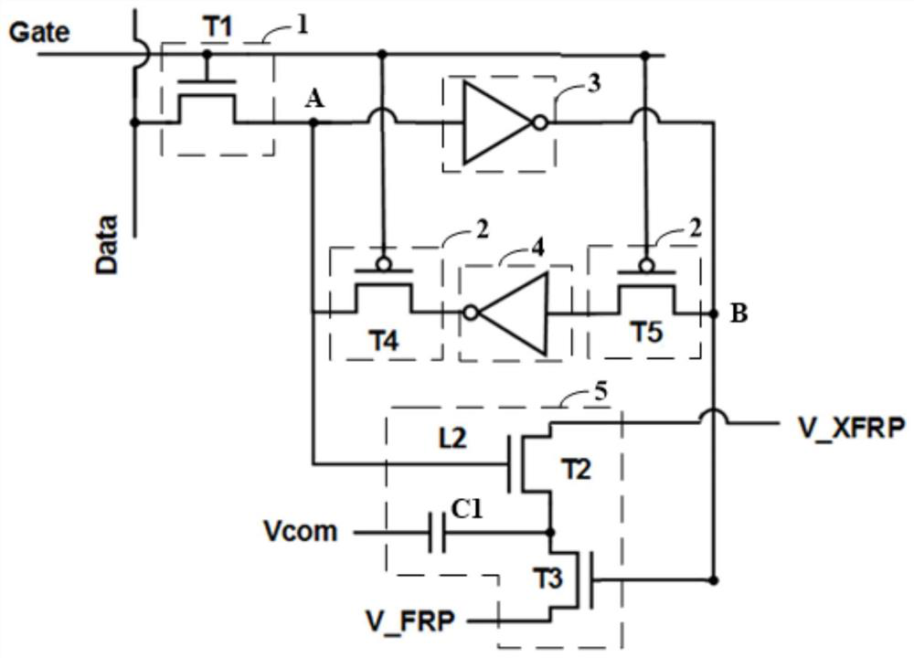
  • Pixel driving circuit, display device and pixel driving method

Examples


Embodiment Construction

[0053]The application is described in detail below, and examples of embodiments of the application are illustrated in the accompanying drawings, wherein the same or similar reference numerals refer to the same or similar components or components having the same or similar functions throughout. Also, detailed descriptions of known technologies are omitted if they are not necessary for illustrating features of the present application. The embodiments described below with reference to the accompanying drawings are exemplary and are only used to explain the present application, but not to be construed as a limitation on the present application.

[0054] It will be understood by those skilled in the art that, unless otherwise defined, all terms (including technical and scientific terms) used herein have the same meaning as commonly understood by one of ordinary skill in the art to which this application belongs. It should also be understood that terms, such as those defined in a ge...


PUM


Abstract

The present application provides a pixel driving circuit, a display device and a pixel driving method, and relates to the technical field of display devices. The circuit includes a first switch sub-circuit, a second switch sub-circuit, a first inverter, a second inverter and a storage sub-circuit; the control terminal and the first terminal of the first switch sub-circuit are respectively configured to be connected with the gate The pole signal line and the data signal line are electrically connected; the first control end of the storage sub-circuit is directly electrically connected to the second end of the first switch sub-circuit, the second control end of the storage sub-circuit is electrically connected to the second node, and the second switch The subcircuit is connected in series with the second inverter. The embodiments of the present application can solve the technical problem of complex operation caused by the need for timing optimization in the prior art, reduce the delay in charging the pixels by the data signal, and thus improve the pixel charging speed of the product. At the same time, the embodiments of the present application can save wiring space in the layout design of the display device, help to reduce the pixel pitch, and improve the product PPI.

Description

technical field [0001] The present application relates to the technical field of display devices, and in particular, the present application relates to a pixel driving circuit, a display device and a pixel driving method. Background technique [0002] With the increasing miniaturization of mobile liquid crystal display devices, small-sized liquid crystal display devices are widely used in daily life. Small-sized liquid crystal display devices mean low-capacity batteries, which need to be charged once a day or multiple times a day. , so that small-sized liquid crystal display devices become a bottleneck for mobile application products. [0003] In order to reduce power consumption, MIP (Mobile Instant Pages, mobile webpage accelerator) technology came into being. MIP technology is to make memory in pixels, and greatly reduce the power consumption of the display device by reducing the refresh frequency. However, in the existing pixel driving circuit, a first inverter and a se...

Claims


Application Information

Patent Timeline
Patent Type & Authority Patents(China)
IPC IPC(8): G09G3/36
CPCG09G3/36
Inventor 王继国樊君
Owner BOE TECH GRP CO LTD
Learn More