
A pressure sensor calibration system for water level measurement in aquaculture ponds

A technology for water level measurement and calibration system, which is used in test/calibration devices, measurement devices, liquid/fluid solid measurement, etc., and can solve problems such as poor measurement data, affecting the measurement effect of the sensor head, and the inclination of the sensor head.

Active Publication Date: 2021-06-22
山东中睿信息科技有限公司
View PDF9 Cites 0 Cited by
  • Summary
  • Abstract
  • Description
  • Claims
  • Application Information

AI Technical Summary

Problems solved by technology

[0007] In order to solve the above-mentioned technology, when the sensing head needs to be placed at the bottom for measurement, the fish inside will fluctuate the water level during the swimming process, causing the sensing head connected by the wire to flutter, causing its PLC programmable controller to sense incorrectly. When it reaches the bottom, it will stretch again. When the sensor head hangs down, it will dump, resulting in poor measurement data. There will be excrement and silt at the bottom of the cultured fish pond. Contradicted by the underlying material, resulting in the tilt of the sensor head or being immersed in the material, affecting the measurement effect of the sensor head

Method used


Image

  • A pressure sensor calibration system for water level measurement in aquaculture ponds
  • A pressure sensor calibration system for water level measurement in aquaculture ponds
  • A pressure sensor calibration system for water level measurement in aquaculture ponds

Examples


Embodiment 1

[0034] as attached figure 1 to attach Image 6 Shown:

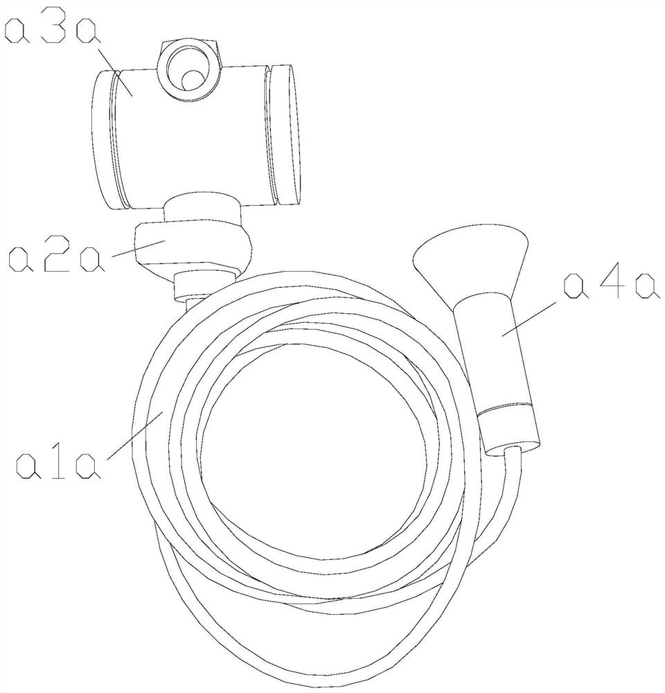
[0035] The invention provides a pressure sensor calibration system for water level measurement in a culture pond, the structure of which includes a conduction line a1a, an expansion joint a2a, a PLC programmable control terminal a3a, and a sensor probe a4a.

[0036] The conductive line a1a is connected to the expansion joint a2a, and the expansion joint a2a is installed on the outer surface of the PLC programmable control terminal a3a, and the end of the conductive line a1a away from the expansion joint a2a is connected to the sensor head a4a.

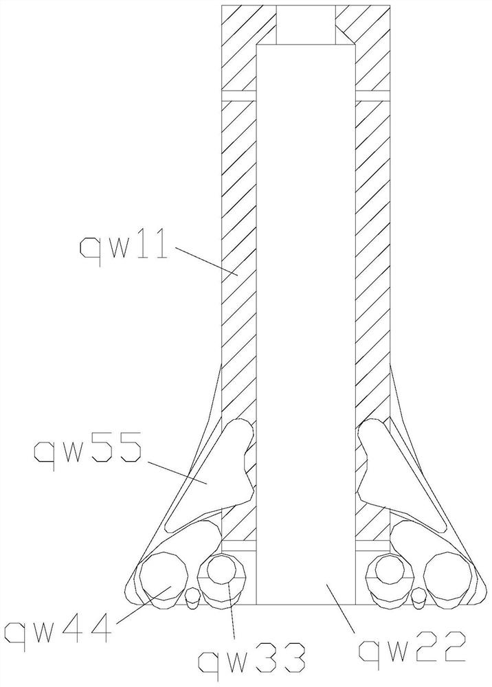
[0037] The sensing head a4a includes an outer limiting shell qw11, an inner channel qw22, a semi-floating body qw33, a stable fork angle qw44, and an inner brace angle qw55. Installed inside the outer limiting shell qw11, the semi-floating body qw33 is arranged on the side of the stable prong qw44.

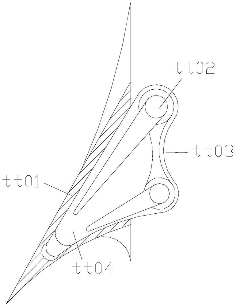
[0038] Wherein, the inner bracing angle qw55 includes an outer pocket tt01, a ...

Embodiment 2

[0045] as attached Figure 7 to attach Figure 9 Shown:

[0046] Wherein, the semi-floating body qw33 includes a vertical ball c10, a buffer layer c20, an inner buoy c30, and a buoyant strip c40, the buffer layer c20 is attached to the outer surface of the vertical ball c10, and the inner buoy c30 is installed on the buffer layer Inside c20, under the buffer layer c20, there is an anti-floating bar c40. The anti-floating bar c40 is in an arc-shaped structure. The vertical ball c10 is a spherical structure. The vertical ball c10 gives a certain gravity to the whole. Extending the area of ​​the connecting parts, the inner buoyancy opening c30 makes the whole have a certain buoyancy, and the buoyancy bar c40 assists the force given by the outer layer to form buoyancy.

[0047] Wherein, the anti-floating strip c40 includes a uniform floating body h11, an outer soft strip h22, an auxiliary buoyancy arc h33, and a movable support bar h44. The uniform floating body h11 is connected...


PUM


Abstract

The invention discloses a pressure sensor calibration system for water level measurement in aquaculture ponds. Its structure includes a conduction line, an expansion joint, and a programmable control terminal. The conduction line is connected with the expansion joint, and the expansion joint is installed on the outer surface of the programmable control end. When the sensing head reaches the bottom, the conductive wire will stop extending down, and it will touch the stable fork angle of the bottom. The angle guides the force direction of the overall conflict, and the rear end is fixed by the middle ball at the force point, and the bottom is supported, so that it can be fixed in time when the sensor head reaches the bottom, so that it will not be affected by the shaking of the water level. Push up, there will be residual substances at the bottom, which will be separated from the water level, and the semi-floating body installed at the bottom of the outer limit shell can smoothly float above the bottom substances when the equipment sinks to the bottom, and can float on the bottom At the same time as there are other substances, the equipment needs to be operated on the bottom layer, allowing it to float in the middle position.

Description

technical field [0001] The invention belongs to the field of PLC programmable controllers, and more specifically relates to a pressure sensor calibration system for water level measurement in aquaculture ponds. Background technique [0002] When it is necessary to measure the water level and pressure in a small fish pond breeding pond, put the device into the water, and the PLC programmable controller will control the sensing head to stop sinking when it touches the bottom of the pond. Water pressure is measured. [0003] Based on the above inventors' discovery, the existing pressure sensor calibration system for water level measurement mainly has the following deficiencies, such as: [0004] 1. When the sensor head needs to be placed at the bottom for measurement, the fish inside will fluctuate the water level during the swimming process, causing the sensor head connected by the wire to flutter, causing its PLC programmable controller to fail to sense the bottom , it stre...

Claims


Application Information

Patent Timeline
Patent Type & Authority Patents(China)
IPC IPC(8): G01F25/00
CPCG01F25/20
Inventor 刘贻刁刘小杰
Owner 山东中睿信息科技有限公司
Learn More