Eureka AIR delivers breakthrough ideas for toughest innovation challenges, trusted by R&D personnel around the world.

Pipe fitting pipe orifice shaping machine used for pipeline welding

A technology for shaping machines and pipe fittings, used in welding equipment, auxiliary welding equipment, welding/cutting auxiliary equipment, etc., can solve the problems of poor shaping effect, incomplete penetration, burn-through, etc., and achieve the effect of stable rotation and easy fixing

Active Publication Date: 2020-05-29
昆山正安流体设备有限公司
View PDF5 Cites 6 Cited by
  • Summary
  • Abstract
  • Description
  • Claims
  • Application Information

AI Technical Summary

Problems solved by technology

[0002]The common connection methods of metal pipes are flange and welding. Insufficient roundness consistency precision at the weld seam will increase the weld seam, which will cause welding defects such as burn-through, missing welding, and incomplete penetration. Then use heating and hammering methods to force the heated part to deform, but this method has poor shaping effect, and it is difficult to maintain accuracy by manual operation. Therefore, we propose a pipe fitting nozzle shaping machine for pipe welding

Method used


Image

  • Pipe fitting pipe orifice shaping machine used for pipeline welding
  • Pipe fitting pipe orifice shaping machine used for pipeline welding
  • Pipe fitting pipe orifice shaping machine used for pipeline welding

Examples


Embodiment Construction

[0020] The following will clearly and completely describe the technical solutions in the embodiments of the present invention with reference to the accompanying drawings in the embodiments of the present invention. Obviously, the described embodiments are only some, not all, embodiments of the present invention. Based on the embodiments of the present invention, all other embodiments obtained by persons of ordinary skill in the art without making creative efforts belong to the protection scope of the present invention.

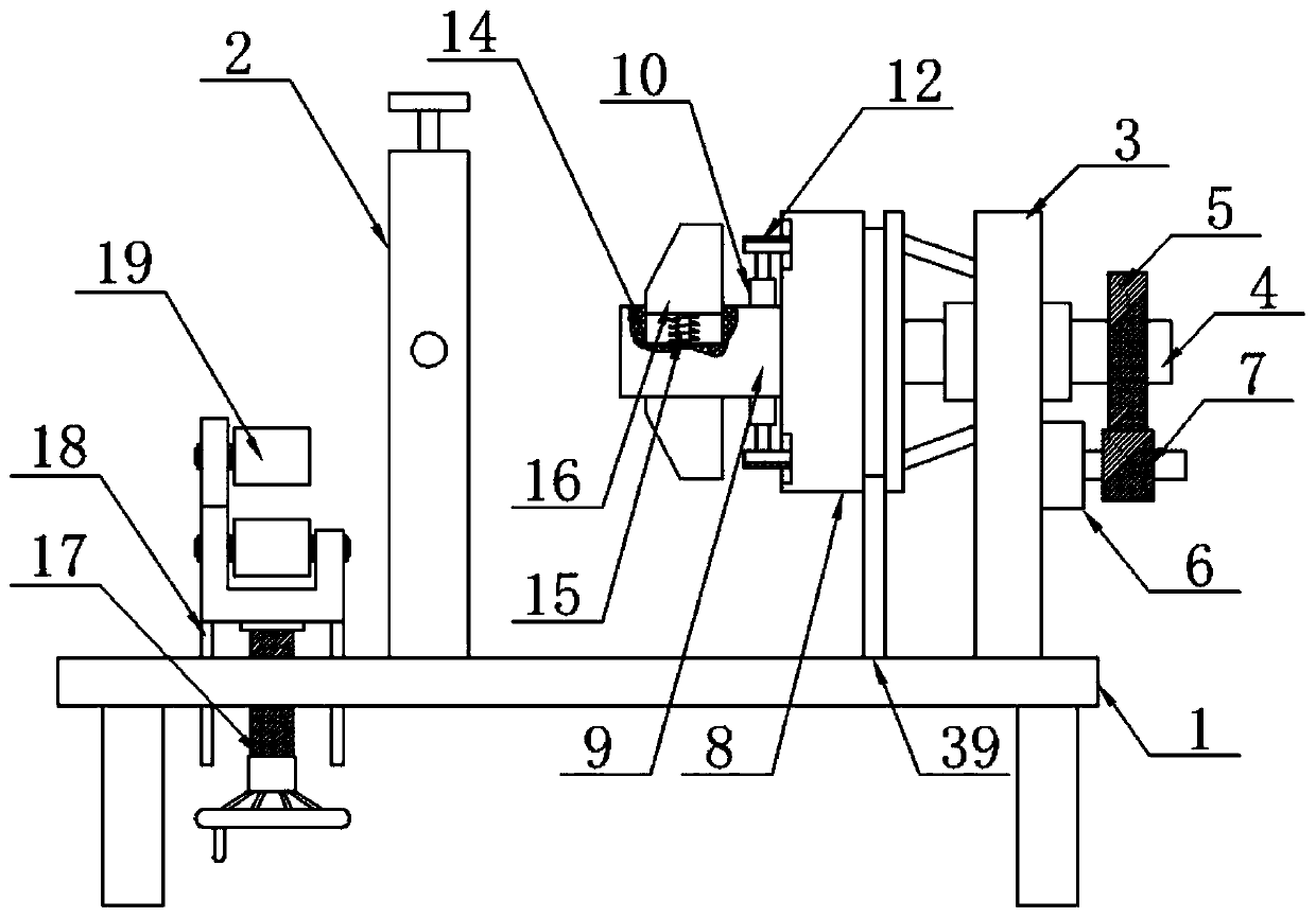
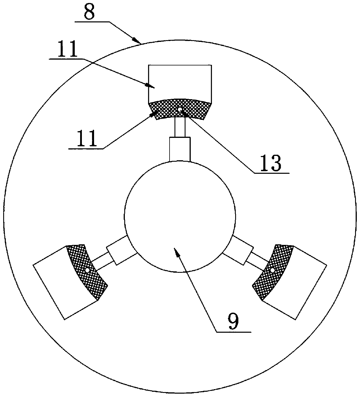
[0021] The invention provides a technical solution: a pipe fitting nozzle shaping machine for pipe welding, please refer to Figure 1-2 , including the base 1, the left and right sides of the outer wall of the top of the base 1 are respectively provided with a pipe auxiliary support 2 and a fixed plate 3, and the top of the outer wall on the right side of the fixed plate 3 is provided with a left and right through mounting hole, and the inner cavity of the moun...


PUM


Abstract

The invention discloses a pipe fitting pipe orifice shaping machine used for pipeline welding in the technical field of pipe orifice shaping machines. The pipe fitting pipe orifice shaping machine comprises a base, a gear is mounted at the power ends on the left sides of motors through a speed reducer, and the top of the gear is engaged with the bottom of a transmission gear. A pipe orifice shaping assembly is mounted at the top of a threaded adjusting rod through a bearing, limiting rods are arranged on the left side and the right side of the joint of the outer wall of the bottom of the pipeorifice shaping assembly and the threaded adjusting rod, and the bottoms of the limiting rods extend to the outer wall of the bottom of the base. After a pipe fitting is fixed, the threaded adjustingrod is rotated so that the pipe orifice shaping assembly can ascend, at this moment, a lower press roller and the outer wall of the bottom of the pipe fitting are located on the same horizontal line,then a lead screw is rotated so that a U-shaped moving seat can move towards the left side, at this moment, the outer wall of the bottom of the pipe fitting is located between an upper press roller and the lower press roller, a threaded rod is rotated again so that a moving plate can descend, at this moment the upper press roller abuts against the inner wall of the pipe fitting downwards, the motors drive the pipe fitting to rotate, and a pipe orifice can be shaped.

Description

technical field [0001] The invention relates to the technical field of nozzle shaping machines, in particular to a pipe fitting nozzle shaping machine used for pipeline welding. Background technique [0002] The common connection methods of metal pipes are flange and welding. When welding pipes, the roundness consistency of the weld joints is relatively strict. If the roundness consistency accuracy at the pipe mouth is not enough, the weld seam will increase. , will cause welding defects such as burn-through, missing welding, and incomplete penetration. At present, the commonly used shaping method is to weld the aligned part at the entire welding joint first, and then use heating and hammering methods to force the heated part to deform, but this The shaping effect of this method is poor, and it is difficult to maintain the accuracy by manual operation. Therefore, we propose a pipe fitting nozzle shaping machine for pipe welding. Contents of the invention [0003] The obje...

Claims


Application Information

Patent Timeline
Patent Type & Authority Applications(China)
IPC IPC(8): B21D3/14B21D43/00B23K37/00
CPCB21D3/14B21D43/003B23K37/00
Inventor 王白石
Owner 昆山正安流体设备有限公司
Why Eureka
Eureka Blog
Learn More