
Cascaded 24-pulse-wave converter topology

A technology of converters and converter groups, applied in the direction of converting AC power input to DC power output, output power conversion devices, electrical components, etc., can solve the problem of insufficient output voltage, high cost, and large actual capacity of transformers, etc. problem, to achieve the effect of load balance and small load

Pending Publication Date: 2020-05-26
SOUTHWESTERN INST OF PHYSICS
View PDF0 Cites 0 Cited by
  • Summary
  • Abstract
  • Description
  • Claims
  • Application Information

AI Technical Summary

Problems solved by technology

[0004] In the prior art, 12-pulse converters, 24-pulse converters and cascaded H-bridges can be used as fast-control power supply topologies, but the disadvantages of 12-pulse converters are: low output frequency, harmonic content Many, and the actual capacity of the transformer is too large, resulting in a huge transformer volume
The disadvantage of conventional 24-pulse converters is that most conventional 24-pulse converters use parallel-connected 24-pulse converters, and the output voltage is not high enough. , the circulating current value will be very large, in order to suppress the circulating current, it is necessary to add a large-capacity circulating current reactor, not only the cost is high, but the volume is also large
The disadvantages of H-bridge cascading are: the structure requires multiple H-bridge modules to be connected in series and parallel, and the topology is relatively complex, resulting in high cost, high output levels, large ripple, and relatively complicated control.

Method used


Image

  • Cascaded 24-pulse-wave converter topology
  • Cascaded 24-pulse-wave converter topology

Examples


Embodiment Construction

[0026] The present invention will be described in further detail below in conjunction with the accompanying drawings and specific embodiments.

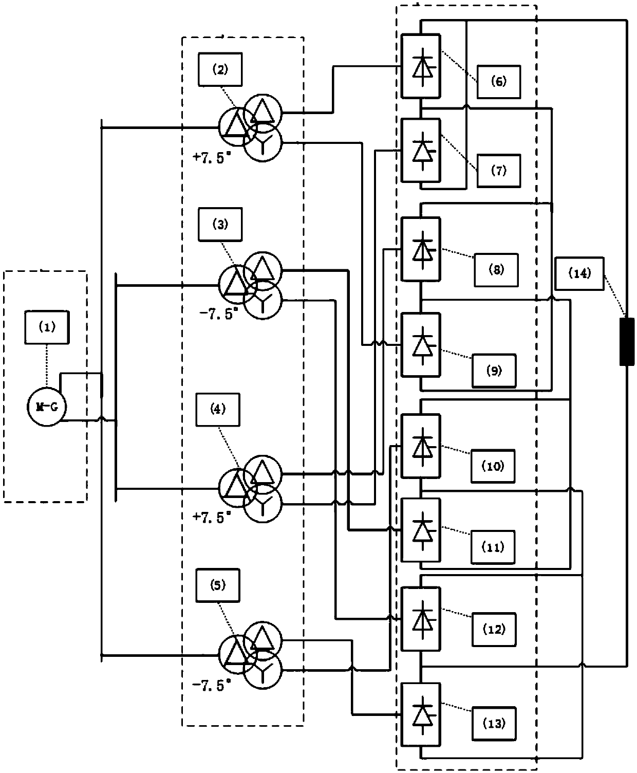
[0027] A cascaded 24-pulse converter topology, including a double Y pulse generator 1, a phase-shifting transformer group, a four-quadrant 24-pulse converter group and a resistance-inductive load 14, and the dual Y-pulse generator 1 is connected to a phase-shifting One end of the transformer group and the other end of the phase-shifting transformer are connected to one end of the four-quadrant 24-pulse converter group, and the other end of the four-quadrant 24-pulse converter group is connected to the resistive load 14 .

[0028] The phase-shifting transformer group includes three-phase double-winding transformer A2, three-phase double-winding transformer B3, three-phase double-winding transformer C4, and three-phase double-winding transformer D5. 476. Step down the high voltage output by the generator and send it to the converter.

...


PUM


Abstract

The invention relates to the technical field of power electronics, and particularly relates to a cascaded 24-pulse-wave converter topology. The cascaded 24-pulse-wave converter topology comprises a double-Y pulse generator, a phase-shifting transformer set, a four-quadrant 24-pulse-wave converter set and a resistance-inductance load, wherein the double-Y pulse generator is connected to one end ofthe phase-shifting transformer set, the other end of the phase-shifting transformer set is connected with one end of the four-quadrant 24-pulse-wave converter set, and the other end of the four-quadrant 24-pulse-wave converter set is connected with the resistance-inductance load. The device can effectively suppress circulating current, omit an additional circulating current reactor, save the costand reduce the size. In addition, once converter fault circulating current is out of control, only the converter connected with the fault converter in parallel is influenced, and other converters arenot influenced, so that other converters are protected to the maximum extent; four-quadrant operation can be realized; the connection mode of the transformer and the converters enables the network side and the transformer to be balanced in load, the transformer is small in load, and circulating current cannot flow through two secondary sides of the same transformer simultaneously.

Description

technical field [0001] The invention relates to the technical field of power electronics, in particular to a cascaded 24-pulse wave converter topology. Background technique [0002] HL-2M is a magnetic confinement nuclear fusion tokamak device in my country. In a tokamak device, plasma control is a very important task. Every plasma discharge and in-depth physical experiment needs to be based on plasma control. . Plasma is the fourth state of matter different from solid, liquid and gas. When performing physical experiments, the plasma will move rapidly up or down in the vertical direction. In order to prevent the plasma from disappearing due to hitting a wall, an active feedback pair is required. It is controlled to generate a magnetic field in the horizontal direction to control the vertical displacement of the plasma, so that the plasma can be stabilized in the horizontal direction and ensure the smooth progress of the physical experiment. [0003] The main task of the top...

Claims


Application Information

Patent Timeline
IPC IPC(8): H02M7/155H02M7/162H02M1/12
CPCH02M7/1552H02M7/1626H02M1/12H02M1/007
Inventor 郑雪宣伟民刘晓龙王英翘
Owner SOUTHWESTERN INST OF PHYSICS
Learn More