Insufficient-driving detection method for screw
A detection method and screw technology, applied in metal processing, metal processing equipment, manufacturing tools, etc., can solve the problems of low detection accuracy of floating locks, long occupation time, complex cost of detection mechanism, etc., and achieve short detection time and reduce complexity. , the effect of high detection accuracy
- Summary
- Abstract
- Description
- Claims
- Application Information
AI Technical Summary
Problems solved by technology
Method used
Image
Examples
Embodiment 1
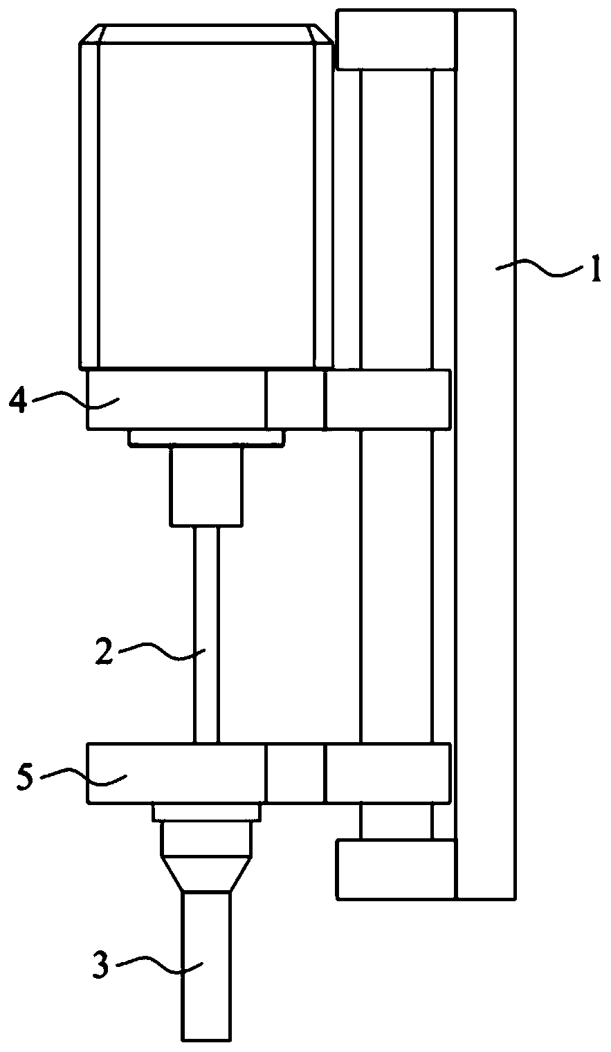
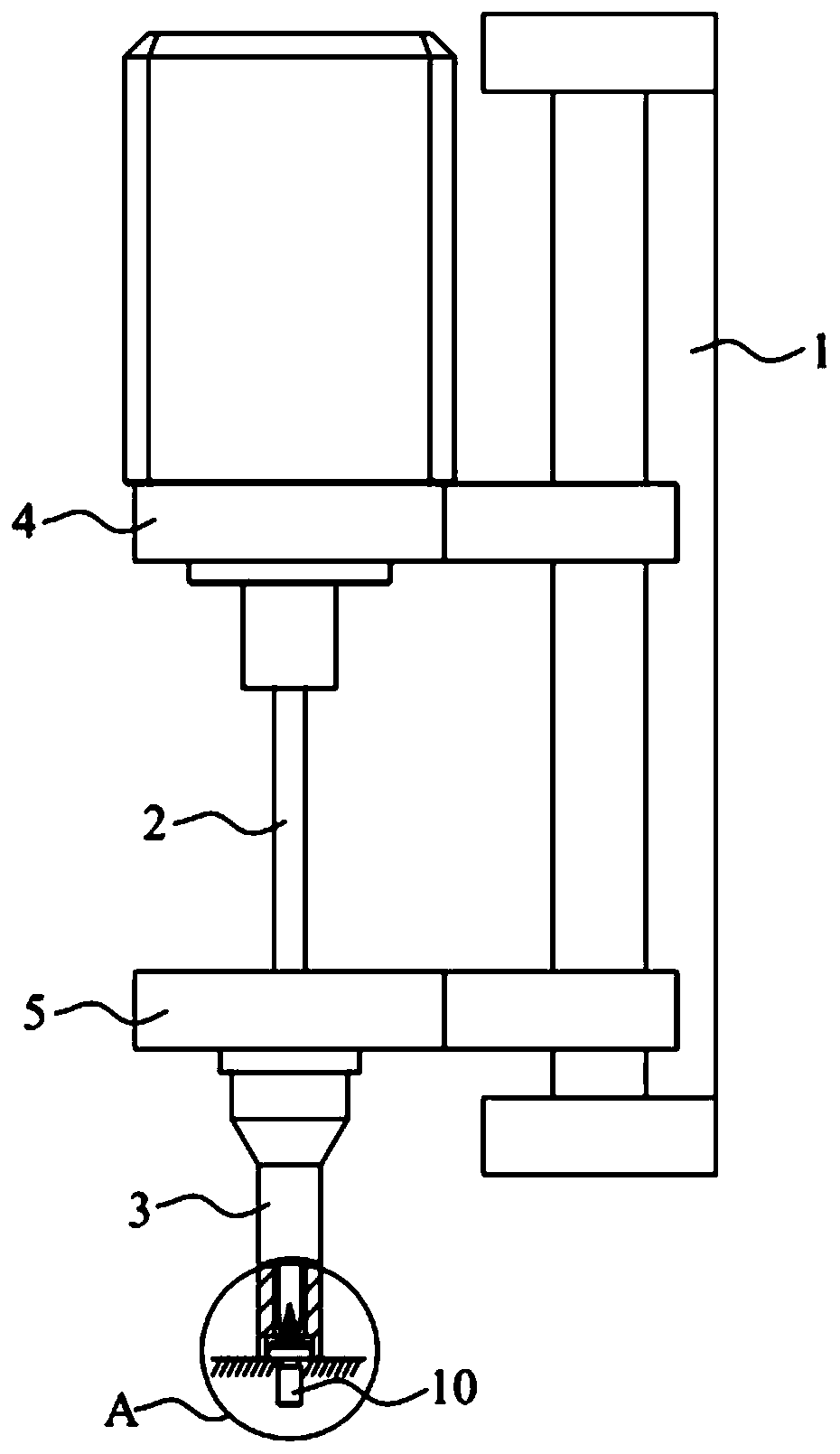
[0042] The embodiment of the present invention also provides a method for detecting the floating lock of the screw, which detects the position during the process of obtaining the screw 10 and when the locking of the screw 10 is completed, without taking up production time.
[0043] Screw floating lock detection methods include:
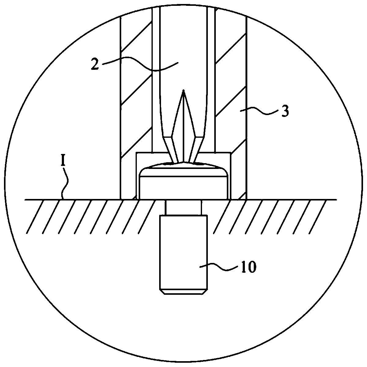
[0044] Acquiring the screw 10: make the end of the positioning part lean against the positioning plane, and control the bit 2 to move along the first direction, so that the end of the bit 2 leans against the screw head;
[0045] Obtain the first distance between the bit 2 and the positioning component along the first direction at this time;
[0046] Locking screw 10: make the end of the positioning part lean against the locking plane, and control the bit 2 to move along the first direction to complete the locking of the screw 10;
[0047] Obtain the second distance between the bit 2 and the positioning component along the first direction when the loc...
Embodiment 2
[0068] For simplicity, only the differences between Embodiment 2 and Embodiment 1 are described. The difference is that the model information of the screw 10 and the pre-stored first distance corresponding to each model information are stored in advance; when the screw 10 is obtained, the model information of the screw 10 is obtained, and the corresponding pre-stored first distance is called; If the obtained first distance is not equal to the pre-stored first distance, an alarm device is triggered so that the problem can be dealt with in time. If the obtained first distance is equal to the pre-stored first distance, the next step can be performed.
[0069] When obtaining the screw 10, the first distance obtained is the distance between the groove bottom of the groove of the screw head and the bottom surface of the screw head. Since for each screw 10, the first distance is a fixed value, it can be measured and stored in advance. , so as to be used for comparison when obtaining...
Embodiment 3
[0072] For simplicity, only the differences between Embodiment 3 and Embodiment 1 are described. The difference is that if the difference between the second distance and the first distance is higher than a preset threshold, the alarm device is triggered.
[0073] When the second distance is greater than the first distance, only the screw floating lock can be judged, but the severity of the floating lock cannot be judged. If the screw floating lock is serious, the distance for the screw 10 to enter the threaded hole is relatively short, and the fastening effect cannot be achieved. At this time, timely processing must be carried out to prevent the quality of the product from being affected.
[0074] In this embodiment, the severity of the floating lock can be obtained through the magnitude of the difference between the second distance and the first distance. If the difference is equal to 0, there is no floating lock. If the difference is greater than 0 and lower than the preset...
PUM
 Abstract
Description
Claims
Application Information
 - Generate Ideas
- Intellectual Property
- Life Sciences
- Materials
- Tech Scout
- Unparalleled Data Quality
- Higher Quality Content
- 60% Fewer Hallucinations
Browse by: Latest US Patents, China's latest patents, Technical Efficacy Thesaurus, Application Domain, Technology Topic, Popular Technical Reports.
© 2025 PatSnap. All rights reserved.Legal|Privacy policy|Modern Slavery Act Transparency Statement|Sitemap|About US| Contact US: help@patsnap.com


