Power distribution cabinet

A technology for power distribution cabinets and cabinet shells, applied in substation/power distribution device shells, electrical components, substation/switch layout details, etc., can solve the problems of maintenance personnel working for a long time, affecting the operation of equipment components, and circuit short circuits. To achieve the effect of humanized design, protection against heatstroke caused by long-term exposure to the sun, and convenient maintenance

Active Publication Date: 2020-05-19
SHANDONG HENGHE ELECTRIC
View PDF8 Cites 1 Cited by
  • Summary
  • Abstract
  • Description
  • Claims
  • Application Information

AI Technical Summary

Problems solved by technology

[0005] In order to overcome the problem that the internal equipment components of the power distribution cabinet will generate a large amount of heat during long-term operation, the long-term internal heat accumulation will cause the internal temperature of the power distribution cabinet to continue to rise, which will not only affect the internal equipment components of the power distribution cabinet. operation, causing a short circuit and causing a fire; at the same time, due to the different environments of the existing power distribution cabinets, some of them need to be placed outdoors. People work for a long time to bring hidden dangers; at the same time, they need to use various tools during maintenance. Maintenance personnel often need backpacks or place them on the ground to repeatedly bend over to pick and place the shortcoming of replacing tools. The technical problem to be solved by the present invention is to provide a Distribution Cabinet

Method used


Image

  • Power distribution cabinet
  • Power distribution cabinet
  • Power distribution cabinet

Examples


Embodiment

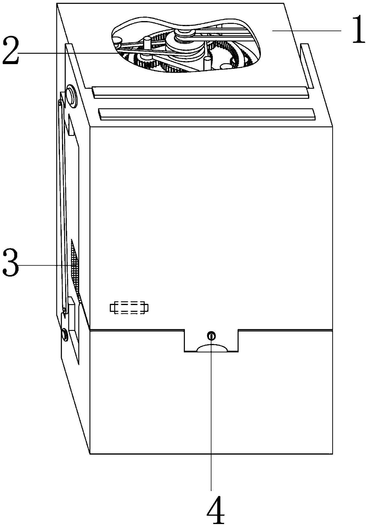
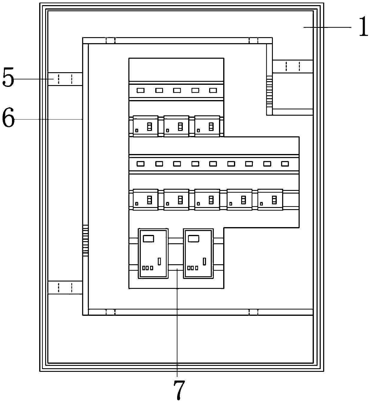
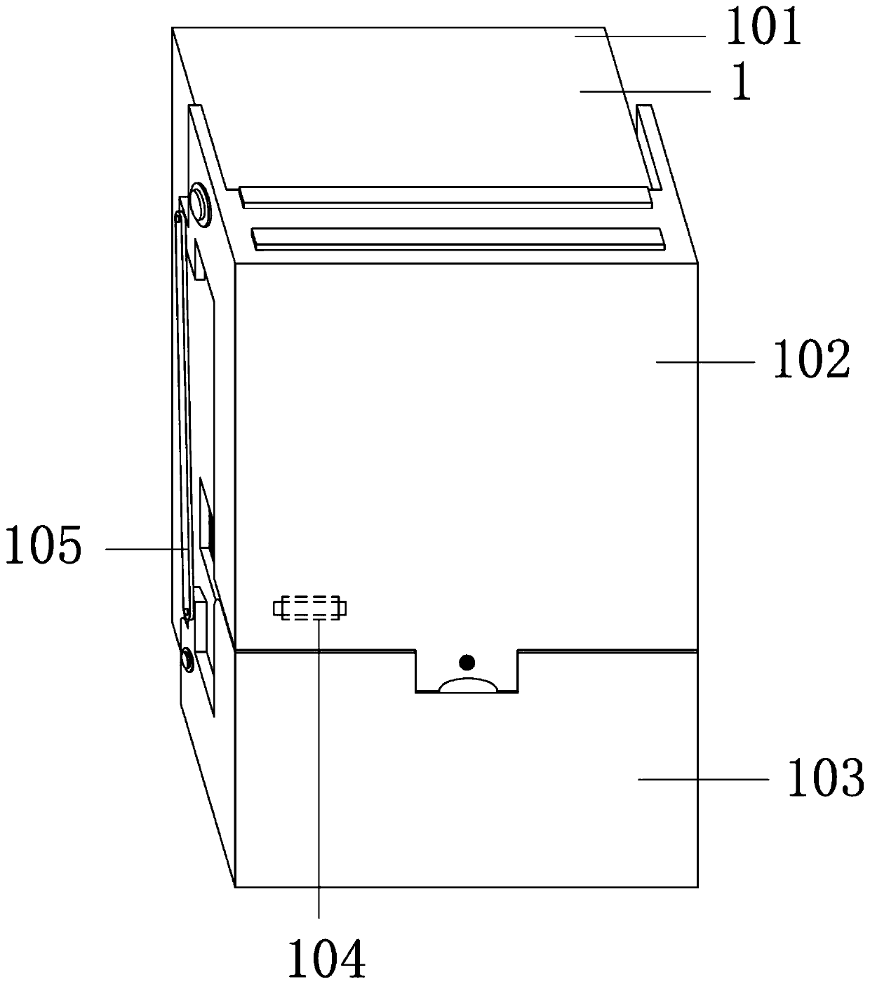
[0031] A distribution cabinet, such as Figure 1-7 As shown, it includes the power distribution cabinet shell 1, the double circulation cooling mechanism 2, the exhaust net 3, the door lock 4, the bearing seat 5, the limit plate 6 and the electric equipment 7; the inner top and the inner bottom of the power distribution cabinet shell 1 , the inner left side and the inner upper right are connected to the double circulation heat dissipation mechanism 2; the lower left middle part of the power distribution cabinet housing 1 is provided with an exhaust net 3; the front, middle and lower part of the power distribution cabinet housing 1 is provided with a door lock 4; The upper left of the electric cabinet housing 1 is provided with a bearing seat 5; the upper middle part of the power distribution cabinet housing 1, the lower part of the inner middle part, the left side of the inner middle and the upper right part of the inner middle are all connected to the limit plate 6; the distri...


PUM


Abstract

The invention relates to the field of power equipment, and particularly relates to a power distribution cabinet. The technical problem to be solved by the invention is to provide the power distribution cabinet. The power distribution cabinet comprises a power distribution cabinet shell, a double-circulation heat dissipation mechanism, an exhaust net, a door lock, a bearing seat, a limiting plate and power equipment. An inner top, an inner bottom, an inner left side and an inner right upper part of the power distribution cabinet shell are connected with the double-circulation heat dissipation mechanism; the exhaust net is arranged below a left middle part of the power distribution cabinet shell; and a door lock is arranged below a front middle portion of the power distribution cabinet shell. Reverse circulation efficient heat dissipation is achieved, meanwhile, an overturning top of the power distribution cabinet shell can shade maintenance personnel, a bottom of the power distributioncabinet shell can serve as a maintenance tool placing table, a humanized design is achieved, a more humanized service is provided, a problem that the maintenance personnel is exposed to the sun and heatstroke for a long time is solved, and meanwhile maintenance is more convenient. Simultaneously, closing and sealing effects are good, and dust can notenter the cabinet.

Description

technical field [0001] The invention relates to the field of electric equipment, in particular to a power distribution cabinet. Background technique [0002] The power distribution cabinet (box) is divided into power distribution cabinet (box), lighting distribution cabinet (box), metering cabinet (box), and is the final equipment of the power distribution system. The power distribution cabinet is a general term for the motor control center. The power distribution cabinet is used in the occasions where the load is relatively scattered and there are few circuits; the motor control center is used in the occasions where the load is concentrated and there are many circuits. They distribute the electric energy of a certain circuit of the upper-level power distribution equipment to the nearest load. This level of equipment shall provide protection, monitoring and control of the load; [0003] In people's life, the power distribution cabinet is one of the indispensable electrica...

Claims


Application Information

Patent Timeline
IPC IPC(8): H02B1/56H02B1/30B25H3/02
CPCB25H3/02H02B1/30H02B1/565
Inventor 马东标
Owner SHANDONG HENGHE ELECTRIC
Why Eureka
Try Eureka