
Time-varying modal parameter identification method

A technology for parameter identification and time-varying modal, which can be used in measurement devices, vibration testing, design optimization/simulation, etc. It can solve the problem of no time-varying modal parameters, and achieve the effect of solving the modal parameter identification problem.

Inactive Publication Date: 2020-05-19
SHENYANG AIRCRAFT DESIGN INST AVIATION IND CORP OF CHINA
View PDF6 Cites 0 Cited by
  • Summary
  • Abstract
  • Description
  • Claims
  • Application Information

AI Technical Summary

Problems solved by technology

[0002] The current modal tests are generally aimed at linear time-invariant systems. For time-varying systems, there is no identification method for time-varying modal parameters in the prior art.

Method used


Image

  • Time-varying modal parameter identification method
  • Time-varying modal parameter identification method
  • Time-varying modal parameter identification method

Examples


Embodiment Construction

[0024] In order to make the purpose, technical solution and advantages of the application more clear, the technical solution in the embodiment of the application will be described in more detail below in conjunction with the drawings in the embodiment of the application. In the drawings, the same or similar reference numerals denote the same or similar elements or elements having the same or similar functions throughout. The described embodiments are some, but not all, embodiments of the application. The embodiments described below by referring to the figures are exemplary, and are intended to explain the present application, and should not be construed as limiting the present application. Based on the embodiments in this application, all other embodiments obtained by persons of ordinary skill in the art without creative efforts fall within the protection scope of this application. Embodiments of the present application will be described in detail below in conjunction with th...


PUM


Abstract

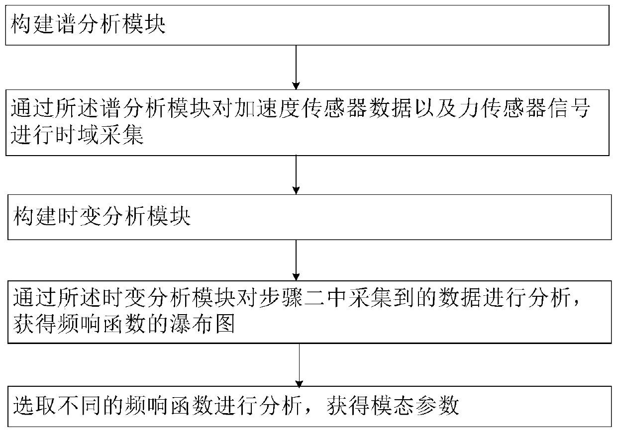
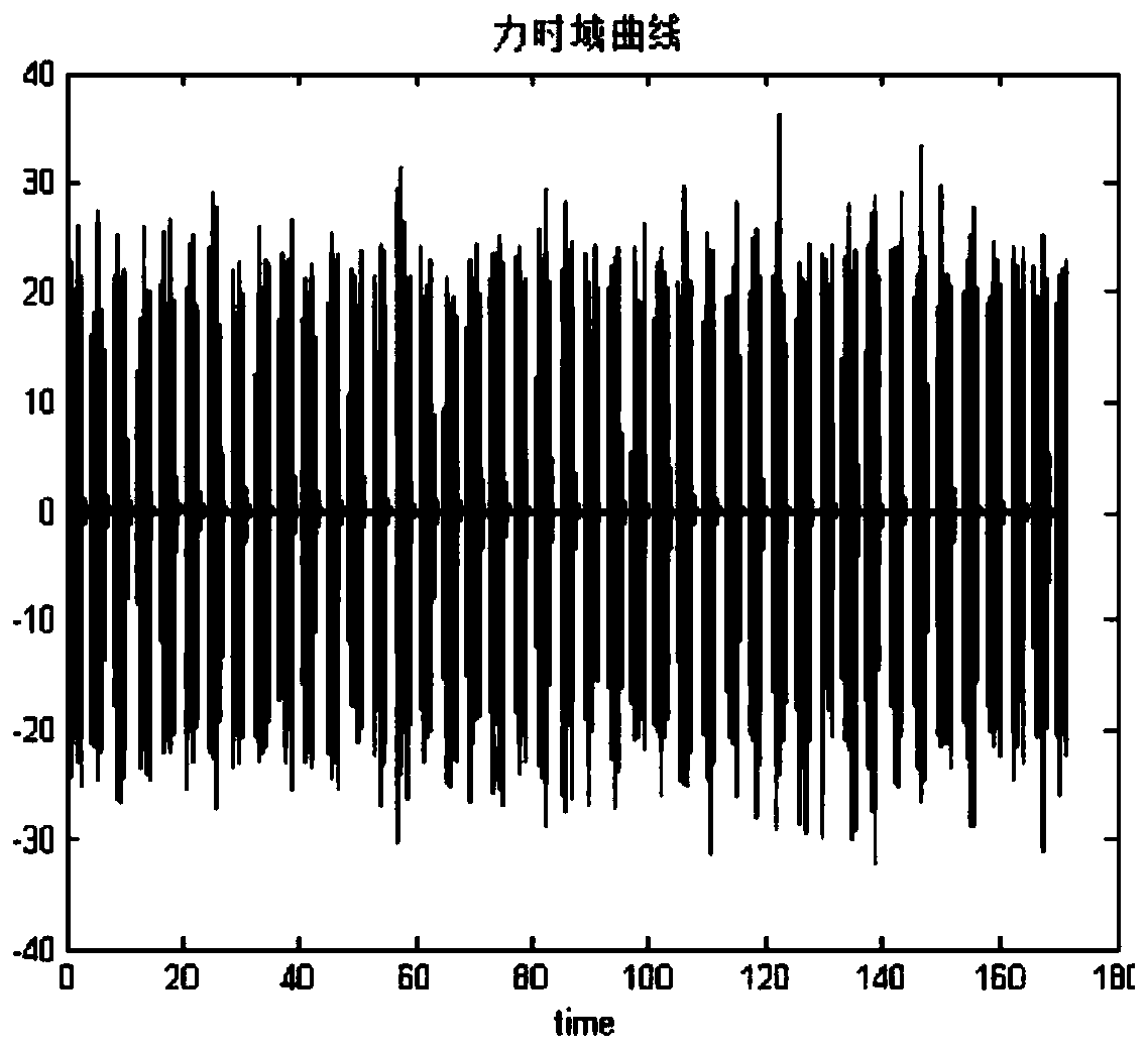
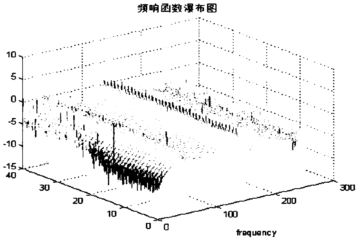
The invention belongs to the technical field of modal tests and particularly relates to a time-varying modal parameter identification method which comprises the following steps: constructing a spectrum analysis module; performing time domain acquisition on acceleration sensor data and force sensor signals through the spectrum analysis module; constructing a time-varying analysis module; analyzingthe data acquired in the step 2 through the time-varying analysis module to obtain a waterfall plot of a frequency response function; selecting different frequency response functions from the frequency response function waterfall plot for analysis, and obtaining modal parameters. According to the time-varying modal parameter identification method provided by the invention, the time-varying analysis module is constructed to analyze the time-domain acquisition data, and finally, the modal parameters are obtained, so that the modal parameter identification problem of the time-varying system can be solved.

Description

technical field [0001] The application belongs to the technical field of modal tests, and in particular relates to a method for identifying time-varying modal parameters. Background technique [0002] Current modal tests are generally aimed at linear time-invariant systems. For time-varying systems, there is no identification method for time-varying modal parameters in the prior art. Contents of the invention [0003] In order to solve at least one of the above technical problems, the present application provides a method for identifying time-varying modal parameters. [0004] The present application discloses a method for identifying time-varying modal parameters, including the following steps: [0005] Step 1, building a spectrum analysis module; [0006] Step 2, collecting acceleration sensor data and force sensor signals in time domain through the spectrum analysis module; [0007] Step 3, building a time-varying analysis module; [0008] Step 4, analyzing the data...

Claims


Application Information

Patent Timeline
IPC IPC(8): G01M7/02G06F30/20
CPCG01M7/02
Inventor 张发明顾亮亮何乾强
Owner SHENYANG AIRCRAFT DESIGN INST AVIATION IND CORP OF CHINA
Learn More